
The latest release of PTC Creo includes enhancements to core tools, a raft of new technologies and more tempting simulation nuggets that look to streamline design work and speed time to market
With Creo 9, released in May 2022, PTC has delivered a host of productivity and usability enhancements that it claims will help users to deliver “your best designs in less time.” In other words, there’s a strong emphasis here on product improvement and faster time to market.
According to Brian Thomson, divisional manager and general manager of Creo at PTC, Creo 9 “is an important release, and our customers’ feedback played a big part in making that happen.”
As an overview of what’s new in the release, Thomson provided the following detail: “We made core improvements, such as the divide surface capability and stronger design intent management to benefit our users. We focused on advanced technologies transforming product design – including simulation, generative design and additive manufacturing.”
And to better support users, Thomson added, “we’ve strengthened Creo’s ergonomics capabilities. All these enhancements are about helping engineers get their best designs to market more quickly.”
There’s a lot packed in to this latest PTC Creo edition – and, according to Thomson and his team, even more enhancements already lined up and ready to be added in when the first maintenance release comes around.
For now, here’s a brief guide to some of the highlights of this Creo 9 release.
Creo 9 // Freeform capabilities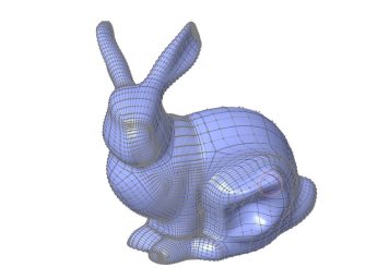
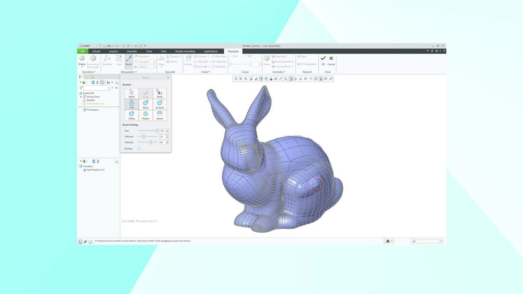
Creo’s Sub-D Freestyle modelling functionality was originally introduced way back in Creo 2.0. This allows users to manipulate a control mesh around a CAD model, which is clearly very useful. In Creo 9, however, PTC has gone further, by adding the ability to modify that mesh using brushes.
What this means is that, instead of picking an individual vertex of the control mesh, users can now use their mouse as a brush. From there, they can choose both the diameter of the brush head and the hardness fall-off, in order to better control the sensitivity of brush strokes that manipulate all of the control vertices touched.
This can then be used to push and pull surfaces as needed, mirror them, or even to attach them to an imported STL file and sculpt over it.
Divide/Unify surfaces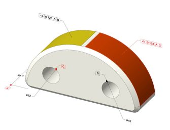
The ability to divide and unify a surface supports a bucketload of valuable use cases. For example, it can be extremely helpful when it comes to rendering aesthetics, simulation load regions, engraving and generative design load and constraint surfaces.
Likewise, it works well in simpler contexts, too, enabling a user to switch a surface colour, so you can find it in an assembly quicker, for example.
The new Divide Surface command inside Creo lets the user take either a given chain of curves, a loop of curves or a sketched entity and project that onto the surface, and split a single surface or multiple surfaces. This allows you to then isolate those surfaces and do your thing. And, should you wish, you can unify the surfaces again using the Unify Surface command.
Curve from point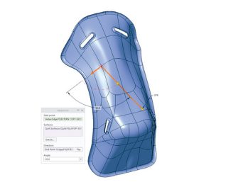
The ´curve from point’ tool in Creo 9 enables users to specify a point on a surface or geometry, give it a direction, and it will then create a geodesic curve between two points that represents the shortest distance following along the surface.
This builds on the geodesic curve functionality introduced in Creo 8 and, in its newest incarnation, may prove particularly valuable for designers and engineers creating composite design products; for example, when a users is looking to lay fabric down over a shape with a straight edge to it and needs to ensure that the material conforms to the shape of their geometry.
Being able to quickly and easily identify this geodesic curve speeds up the overall design process and provides users with an additional level of control.
Creo 9 // Custom mannequins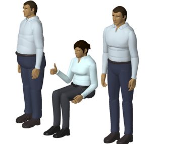
Expanded ergonomic tools have been included in this release, in order to help designers create products that comply with safety, health and workplace standards.
While Creo has shipped for years now with a library of mannequins built to fit specific standards, some customers said that they wanted to be able to create their own custom dummies to fit specific demographics. Creo 9 now includes this capability.
Mannequin reach has also been added as a constraint: this means that if changes are made to a CAD model, the model will regenerate and so will that constraint. If, for any reason, a mannequin is unable to reach a particular area, it still moves to its extremities of reach, but Creo displays a dimension that tells the user how far short of that location it is.
Creo 9 // Fliud flow lattice simulation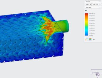
Creo 9 also sees an expansion of formula-driven lattice structures to create gyroids. That’s great for a snazzy concept of a heat exchanger, but it’s a capability that Creo 9 backs up by enabling users to perform fluid flow simulations using Creo Simulation Live.
PTC has worked hard to make these features more user-friendly, with an ‘initial simulation’ option available. This enables users to quickly ensure that a given optimisation study is set up correctly, saving them valuable time that might otherwise be spent making painstaking corrective tweaks.
PTC has also introduced support for variable wall thicknesses, allowing users to vary thicknesses, to block off volumes entirely, as well as to explicitly control how fluid will flow through a product.


