
Full release showcases enhancements to core tools, new technologies and further simulation nuggets from Ansys that all look to enable better designs in less time for PTC Creo 9 users
PTC has showered us with a constant flow of updates for its Onshape product, but the big annual update cycle remains for its most powerful 3D CAD software, Creo, and release 9 is one that has had many users guessing.
PTC Creo 8 showed that the company’s acquisitions and partnerships (notably with Ansys) had created a maturing technology, while its machining tools were brought bang up to date.
At first glance much of PTC Creo 9 looks to be about improvements to performance and workflow, and on paper there are plenty of general enhancements, workflows, functionality improvements and little tweaks that every single user can take advantage of straight off the bat.
Yet we were lucky enough to dig a little deeper and gain the insights of Paul Sagar, PTC VP of product management, along with PTC’s CAD Division VP and GM Brian Thompson about some of the key areas of improvement PTC has focussed on in Creo 9.
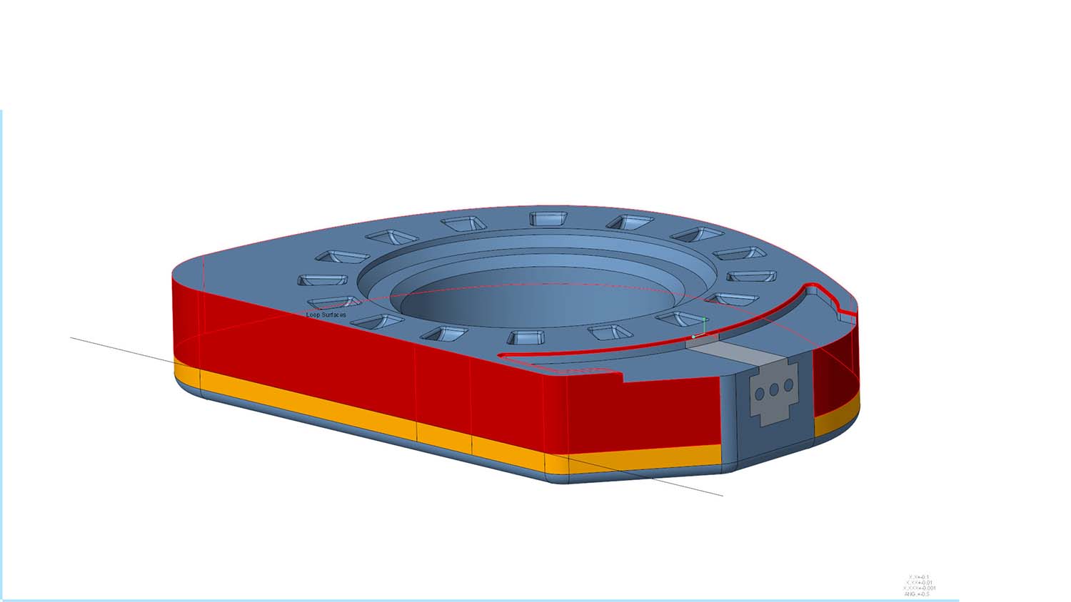
The first they were keen to show me has instant benefits – the ability to divide and unify a surface. It’s helpful for rendering aesthetics, simulation load regions, engraving and generative design load and constraint surfaces – but in more simple terms it can allow basic things like switching a surface colour so you can find it in an assembly quicker.
The new Divide Surface command inside Creo lets the user take either a given chain of curves a loop of curves or a sketched entity and project that onto the surface, and then split a single surface or multiple surfaces into many more surfaces. This allows you to then isolate those surfaces and do your thing, and should you wish you can unify your surfaces again using the Unify Surface command.
“It’s an item that is crucial as companies are moving towards Model-Based Definition (MBD),” says Sagar. “And they need to capture that rich information in a 3D model. But also for the purpose of simulation, when you want to have greater control over the exact area where a particular load or constraint is applied to.”
The ‘general updates’ continue to come thick and fast.
Updates to the model tree in Creo 9 look to make it faster to structure, document, and understand design intent, building on the Design Item Tree introduced in Creo 8.
A new Quilt/Body Evolution Tree is employed to give a structured view of how your model is built up. So not based upon the features or the history, but based upon the structures to give the users a clearer understanding of the structure of the model.
As Sagar explains: “If I’m a user that maybe didn’t design the model originally, I can now clearly come in understand the structure of the model, understand the history of the model, and understand certain groups or documented aspects of the modelling to help me more easily and intuitively understand the impact of changes that I might make on the model and helped me understand more easily what aspects I need to change what features I need to change to alter the model.”
There’s a new toolbar across the top of the Tree to give easy access to the variable commands, making it easier for users to alter the display for instance, or to go about inserting into the model tree.
Creo 9 // Starting out
A key tool in any CAD package is the sketching environment, and Creo’s has received upgrades for this version launch, helping to define those initial dimensions and scale the rest of the dimensions in that sketch to maintain the aspect ratio of that particular shape. With that first modification, any subsequent modifications you do will then act on the individual dimension. But the first one will scale the entire sketch, making this an easy win for all users.
There’s been work done to improve the diagnostics tools inside the sketcher, so that once you turn on Diagnostics, it will keep intersection points highlighted on the screen, along with any overlapping geometry highlighted, just as a means to make it easier for the user to understand the geometry that’s on the screen and identify any potential problems.
A Curve From Point, tool allows users to specify a point on a surface or geometry, give it a direction, and it will then create a geodesic curve between two points that is the shortest distance following along the surface.
“This is actually really important when you start looking at building composite design products,” interjects Sagar. “Where you’re looking to lay fabric down over a shape and you need to make sure that obviously as you’re laying that the fabric has a straight edge to it. And so you want that fabric to conform to the shape of your geometry.
“Being able to identify quickly and easily this geodesic curve speeds up that overall design process.”
A number of improvements have been made to Patterns in Creo 9. A quick example is around patterning a hole feature, both Simple Holes (punching a hole through your model at a certain diameter) and Standard Holes (an M16 hole with a particular thread associated with it, for example). Previously, once these were patterned that was it – no ability to change this. Now you can change a hole type from simple to standard without having to go and redo, delete, and recreate the pattern.
Elsewhere, Patterns have seen performance improvements – one of the options is a geometry pattern that can take a group of features that create some geometry and it then go and pattern it across your model. When you pattern it, as long as what the geometry is intersecting with is the same type of geometry – for example, if you’re Patterning along the planar surface, you know, the intersection is going to be the same – Creo 9 has added in the option to do an identical pattern. Sagar says that this has resulted in significant performance advantages – cutting down one example he showed us from 50 seconds down to a mere two.
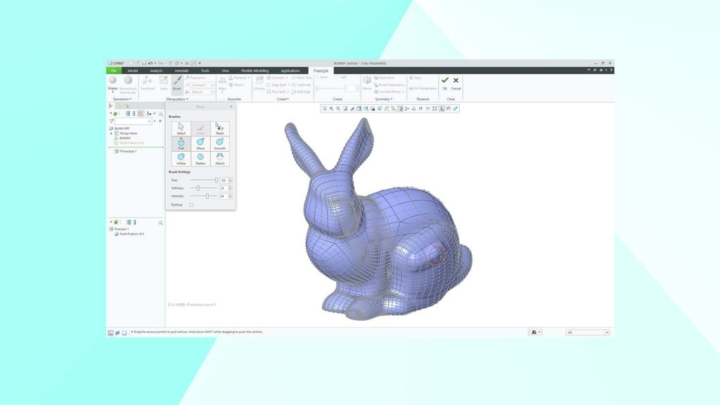
One of the interesting new updates in Creo 9 is found in Creo’s Sub-D Freestyle modelling capabilities. This Freestyle functionality has been kicking around for nearly a decade, since Creo 2. As you’d expect, it allows users to manipulate a control mesh around a CAD model, but in Creo 9 PTC has added the ability to modify that control mesh using brushes. So instead of picking an individual vertex of the control mesh, users can now can use the mouse as a brush, with the ability to choose the diameter of the brush head and the hardness fall off, to better control sensitivity or intensity of the brush strokes which can manipulate all of the control vertices that the brush is touching.
This can be done to push and pull the surfaces, mirror them, or even attach the surfaces to an imported STL file and sculpt over it, and was one of the features Brian Thompson was keen to highlight, describing it as ‘very cool and extremely productive’. “It just adds a really awesome dimension to a product that customers will already really like. I think they’re gonna love that even even more!” he says.
Creo 9 // Design for dummies
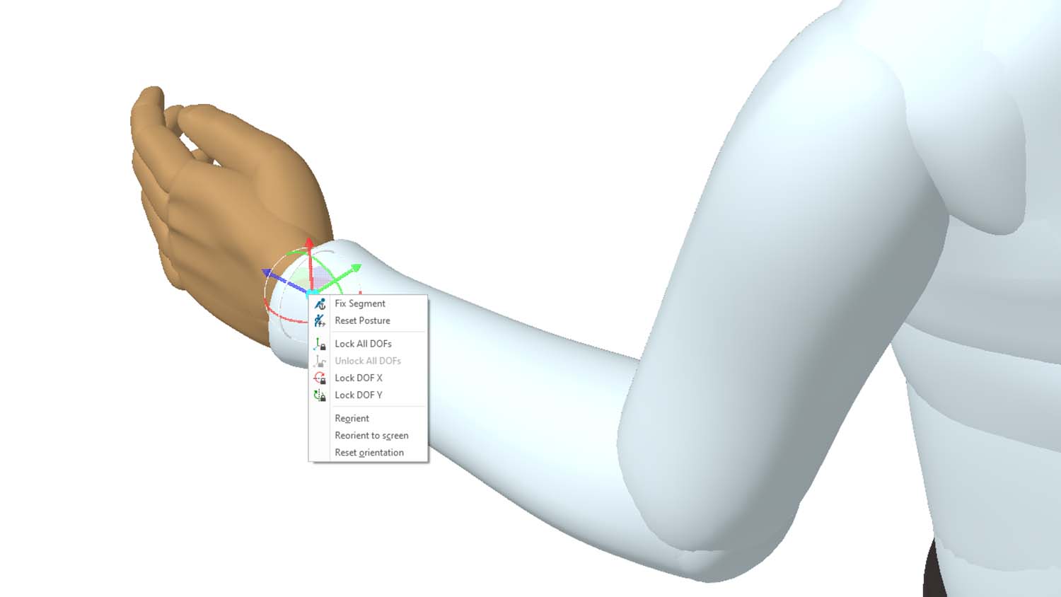
Expanded ergonomic tools have been added to this release to help designers create products for all users, and to help them comply with safety, health, and workplace standards that differ around the world.
While Creo has shipped for years now with a library of all the standard mannequins to fit certain standards, some customers still wanted to be able to create their own custom dummies to fit some specific demographics that they sell their product to, and Creo 9 has accommodated this. PTC has also added the ability to add that reach as a constraint. What that means is when a physical constraint is defined, and then if changes are made to the CAD model, the model will regenerate and so will that mannequin constraint. If for any reason that the mannequin is unable to reach that particular area, the mannequin still moves to their extremities of reach, but Creo now shows a dimension that tells you how far short of that location it is.
In addition to mannequins, a new Vision Field Analysis capability has been added to allow engineers to analyse a product user’s line of sight and field of view – such as from the driver’s seat of a new car model – to help prove and validate a design long before designers are far down the development path and facing lots of costly changes.
Model-Based Definition (MBD) has been a key theme of every release of Creo for some time now, and Creo 9 sees continued investment – especially in surface finishing and welds, which means users can include specialised downstream manufacturing information right on the model, for better efficiency and communication.
PTC says this is becoming more important as more companies are transitioning to ‘3D-centric processes’ as they jump onboard with the digital thread throughout their entire organisation.
The number of symbols has grown and modernised, and there’s expanded support for surface finishes as well. This latter part adds a bit of intelligence to the system that now understands not only that it’s a surface finish, but also understands what surface you’re putting it on, as well adding as a new gallery of surface finishes and three new ASME/ISO standards.
Automated weld symbols, created based upon weld features that you add, make up a nice new feature in MBD, automatically creating the weld symbol and populating it with the appropriate parameters that are directly coming from the weld fixture itself. Change a weld feature’s size, for example, and those parameters will automatically be updated.
GD&T Advisor improvements in Creo 9 see improved support of detailing standards for better drawing quality and increased productivity, and in short all seemed designed for ease of access, streamlined creation and overall better usability. An example is the cross highlighting between the geometry in the graphics area and the annotation in the model tree. This aims to make it easier for you to be able to figure out which annotation in the model tree and the graphics area apply and then make appropriate changes – whether in the model tree or changes from directly from the graphics area.
For those still requiring 2D drawings in their workflows, they’ll be delighted to see a whole host of new hatching and shading options.
Creo 9 // Additive and Subtractive
Back into 3D and it wouldn’t be a 2020’s CAD product release if it didn’t bring up generative design or lattices, and while prior release have had these tools up top in the product launches, in Creo 9 this was showcased as a more mature tech, rather than some glitzy hype.
“We’ve got many customers that are aggressively looking at generative design to look to improve their business processes reduce the time to market whether it be saving costs by reducing the weight of components, etc. So we’ve continued to make enhancements to generative design, and also our simulation driven design strategy,” explains Sagar, reminding us that PTC’s policy is to leverage the trusted solvers of Ansys and fully integrate them into the Creo suite of products.
That’s not to say PTC hasn’t been busy: “In Creo, nine, we’ve expanded [generative design] by adding support for a safety factor,” explains Sagar. “So now if I’m doing a structural optimisation, I can tell the system to go minimise the mass of my component but minimise it to a certain target safety factor. And based upon the material I’ve got, based on the safety factor of that particular material, it will lead you on generating your optimal design for you.”
Creo 9 has also added modal optimisation, allowing users to maximise a particular fundamental frequency based upon a certain target mass or volume of material. Or conversely, if you want to minimise the mass to achieve a certain minimum.
Within the context of assemblies, users are now able to specify ball joints with the appropriate loads and constraints associated with those.
Creo 9 also sees the expansion of formula driven lattice structures to create gyroids – great for a snazzy concept of a heat exchanger, but something that Creo 9 backs-up with the ability for users to do fluid flow simulations using Creo Simulation Live. It has worked to make these features more user friendly, with Initial Simulation quickly ensuring that an optimisation study is set up correctly, before you waste your time. Equally, is making the lattices useful: in a heat exchanger, for example, it’s simple to block off some of the gyroid volumes, add an inlet and outlet port, and to control how the fluid will transfer through the product. Again, to make this work the best it can, PTC has introduced variable wall thicknesses that allows users to vary the thicknesses (and easily block off volumes) and explicitly control the flow.
Creo Simulation Live maintains its focus on offering designers the ability to do fast-and-early simulations, with enhancements added to performance in order to speed-up analysis that can help change the direction of a design. Sagar adds that with a maintenance release available around June 2022 PTC will add contact simulation inside Creo Simulation Live as well – giving greater control of how components interact with each other in an assembly environment.
Creo Ansys Simulation remains for those big, higher fidelity final simulations in the development process. Among the new features here are some solver updates and added support for bearing loads.
“Bearing loads are somewhat unique in the fact that the volume is applied normal to the surface of the bearing,” says Sagar. “This allows us to more realistically represent the bearings inside your design.”
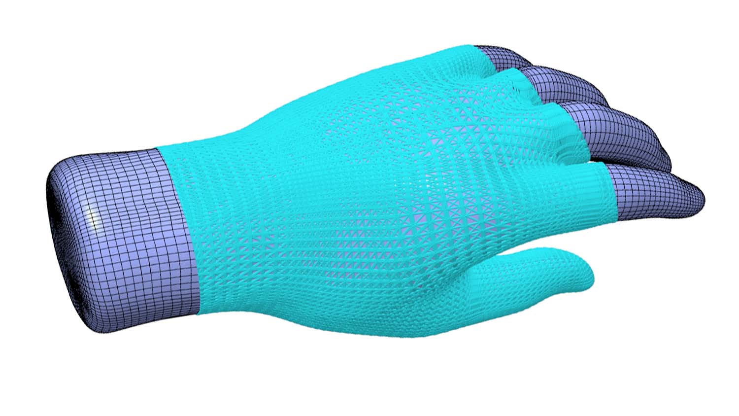
Advances in additive and subtractive manufacturing in Creo 9 flow on nicely from the generative design updates, delivering improved control over stochastic and formula-based lattices and allowing user-defined support structures for advanced additive manufacturing use cases.
“We’ve done a lot of work on improving geometry robustness here to enable us to build more complex geometric scenarios where I’ve got lattice structures over my entire design,” explains Sagar.
In terms of machining, PTC says it has been building out its high speed machining capabilities, starting with roughing and re roughing. In Creo 8 it added support for 3- to 5-axis machining, and in 9 it validates full 5-axis geodesic machining of toolpaths to speed up the process.
The example Sagar gives is an octagonal shape with multiple pockets that need to be machined. Previously these would have had to have been independently selected in a fairly time consuming operation. Now you simply give the software the entire model, and the system will then go and figure out what is the optimal path as to how to go and generate that particular full 5-axis tool path.
There’s also the introduction of adaptive feed rates, that will accelerate or decelerate the cutting tool appropriately as the tool is coming to a change in direction. Firstly, this reduces the chatter of the tool as it starts approaching a tight corner thereby increasing the lifespan of that cutting tool. It also results in better surface finishes on your final pass.
The majority of the subtractive upgrades have been focussed on production manufacturing capabilities, with a bundle of user driven enhancements such as adjustments to the stock model and where users want the optimal toolpath because they’re machining the same thing 1,000 times a day.
“What customers used to do would be to go and generate the toolpath and then maybe go in manually,” says Sagar. “Before post processing, what we’ve done is taken a lot of that information and expose that directly inside Creo. So now in the case of turning operations, you have the ability to split turning profile passes and CL commands have greater control of how the tool is going to enter and exit and this particular tool paths.”
Creo 9 // Verdict
There’s a lot packed in to this latest PTC Creo edition, with more already lined-up to be added-in come the first maintenance release, something not lost on Brian Thompson, who reaffirms the message. “Just keep in mind,” he says at the end of our meeting. “That’s one development year… I think it’s a very impressive result by the team – an incredible amount of capability added to the product.”
He’s not wrong. In the ever competitive field of workhorse 3D CAD systems, there seems to be no let-up in adding new features and ramping up the speed and usability of existing tools, and to this extent Creo users have a lot of new updates to look forward to that have been designed to fit easily into their existing workflow.


