
Military aircraft programs have been the proving ground for carbon composite materials. Usage has now crossed over into commercial aircraft, and other areas, where these materials offer significant benefits over their metal counterparts. Corrosion and fatigue of aluminium airframes and surfaces, for example, makes maintaining these aircraft increasingly expensive. Composite structures, on the other hand, remain chemically inert, whilst being stronger and lighter than metal.
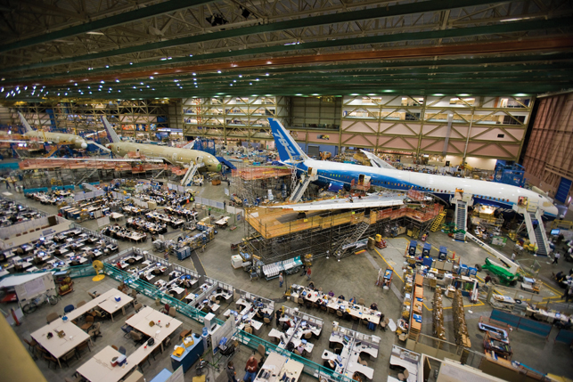
The Boeing 787 Dreamliner will have 50% of composite materials by weight, compared to just 10% in the Boeing 777; and the Airbus A350 XWB will have 52% by weight, compared to 23% in the A380.
So what are these new materials and techniques? In general composites consist of a fibre structure inside a matrix of resin, where the resin protects the structure and holds it in place; loads are transferred to the fibre structure which acts as a reinforcement. Glass is still probably the most-used fibre, but increasingly graphite (carbon) and aramid, known by the trade-name Kevlar or Twaron, are used. Resins typically comprise two types: thermosets (which cure permanently when heated) and thermoplastics (which soften when re-heated).

Exactly half of Boeing’s 787 Dreamliner is made out of composites materials. Images courtesy of the Boeing Company
Material is laid-up on a tool or mould to form the composite part using various processes. There are four main composite manufacturing processes: Laminate Ply, Tape Laying, Fibre Placement and Resin-Transfer Moulding. The part produced is then cured or hardened in an autoclave or industrial oven; some parts require placing in a vacuum bag inside the autoclave to ensure proper resin transfer across the whole part. The main difference between these processes and traditional production methods is that they add, rather than take away, material. Currently, much of the lay-up process is undertaken by hand and processes like Resin-Transfer Moulding and Laminate Ply are still labour-intensive.
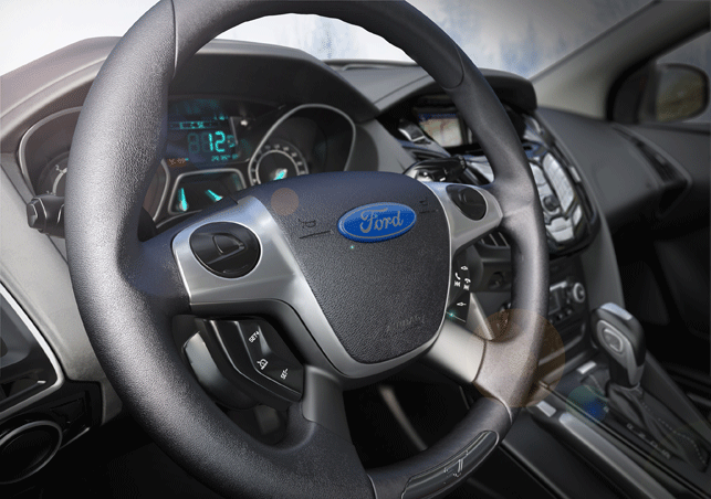
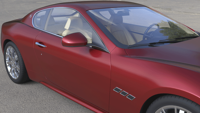
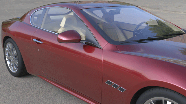
Uptake of composites in automotive is increasing, but it will be at least five to ten years before they are more widely used in production models
AdvertisementAdvertisement
The software challenge
This produces new challenges for software suppliers who supply design and manufacture systems for composites. The major vendors, such as Siemens PLM Software and Dassault Systèmes rely on close cooperation with Airbus and Boeing to develop design solutions, often in association with small developers close to the production facilities. Vistagy, a Waltham, MA-based company, is a recognised leader in Composite Design environments, which integrate with all the leading CAD/PLM systems. MATERIAL, a Belgian developer, is a leader in Filament Winding software with CADWIND. Tooling, such as wing panels and fuselage sections, upon which material is laid-up, is similar to that used in conventional mould and die and flat-pattern development. Manufacturing software suppliers like Siemens PLM Software, Delcam and JetCAM are already developing their business in this area. Specialised cutting, drilling, fixtures and tooling are still required to suit the particular type of composite being prepared.
Driving Composites machines
Many of the machine-tool suppliers provide their own programming solutions to drive composite machines; these can be very large (tens of metres long and wide) and operate on up to 7-axes, to apply material at the correct angle and thickness. There are three main types of machine for material placement: Automated Tape Laying (ATL), Automated Fibre Placement (AFP) and Filament winding (see box out). Other machines are used for cutting and preparing the material for lay-up and for trimming and drilling the finished part.
NC machines for material placement
Automated Tape Laying (ATL) – A numerically-controlled (NC) machine which is mainly used for flat, or near-flat, parts with uniform, or near-uniform, thickness. This limits the class of parts produced, but is quick and cost-effective (compared to manual methods). Tape, with unidirectional fibres, rather than the bi-directional fibres of woven tape, is usually pre-impregnated with resin and applied wet, though in some cases, dry-fibre, without the resin, is used. The tape is applied by a delivery head over the tool surface in a repetitive pattern to form a ply. Plies are usually built from alternate crossing patterns to produce a finished laminate with homogenous strength. Standard tape widths are 3”, 6” and 12”. Wings are an example usage.
Automated Fibre Placement (AFP) – A numerically controlled machine which is similar to an ATL but which uses a strand comprising up to 32 composite “tows”, instead of a tape. Each “tow” is a pre-calculated bundle of fibres, usually 0.125” to 0.250” wide. The main advantage of fibre placement over tape is having the ability to produce parts that have a higher degree of contour and complexity, such as aircraft fuselage panels, than can be produced using an ATL. Individual tows can be dropped and started separately, to eliminate buckles and wrinkles and adjust the width of the tow to fit into a tapered shape.
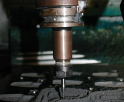
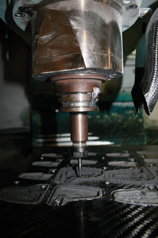
Specialised cutting, drilling, fixtures and tooling are required to suit the particular type of composite being prepared. Image courtesy of Delcam and Crosby Machining
Filament Winding – A variation of fibre-placement, the delivery head (or mandrel) is cylindrical in shape and spins on a lathe during the winding process. The resulting fibre tow is dispensed by a pay-out eye, which travels back and forth whilst the head is rotating, and can also be oriented to lay the fibre at various angles. The disadvantage of this technique is that the head does not have the compaction of an ATL or AFP, relying on the contour of the part to apply tension to the tow. Hence, convex shapes are not suitable for filament winding. Examples of parts produced using this technique include aircraft fuselage skins and fuel tanks.
Leading ATL vendors in aerospace include MAG Cincinnati, Ingersoll, Forest Line, ElectroImpact and M Torres, plus smaller players like American GFM and Accudyne Systems. Some of these vendors also provide composite design and manufacture sub-contracting services, providing a proving-ground for new technologies. This reduces the risks of using composites for their customers and promotes the take-up by industry. Our estimates suggest an installed base of around 120 ATL machines worldwide.
There are fewer AFP machines installed – perhaps 75 – with the leading vendors, in this case MAG Cincinnati, Ingersoll and lastly, Forest Line, working closely with Boeing and Airbus. These vendors also supply the controllers and CNC programming systems in a total “Composites solution” for their customers. Since volumes are small, many machines are “customized” to meet specific manufacturing requirements; this is a challenge for manufacturers, since uptake of composite parts is inhibited by the lack of “standard” machines at reasonable prices – a large ATL or AFP can cost several million dollars. Growth in the number of ATLs and AFPs required depends heavily on the production ramp-up of the current and next generation of commercial aircraft.
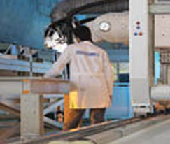
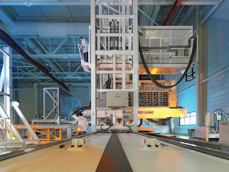
Fibre lay-up at Airbus. Image courtesy of Forest-Line
Some machine tool suppliers, including Zund, Gerber and Eastman, focus on cutting of the ply, or Filament Winding, like Entec and EHA. Others, such as Automated Dynamics, produce delivery heads and systems, rather than the whole machine, aimed at flexible and smaller-scale production. The smaller vendors often look beyond aerospace into adjacent industries, where composite materials also have very obvious benefits. These applications include drilling operations under high pressure and temperature; new, high-speed train networks, where weight and physical performance reduce lifecycle costs; turbines for wind-farms, where the weight and performance of the blade are directly linked; and corrosion-free storage for volatile liquids and fuels, such as petrol tanks and gas-bottles.
Market potential
Automotive is an obvious market for composite parts – carbon-fibre is already used in F1 and high-end sports cars – as the associated weight savings go some way to increasing the overall energy efficiency of a vehicle. A number of issues need to be addressed before we see wider adoption, however, not least the availability of materials. Aerospace consumes almost all the carbon fibre and resin currently in production, paying a premium to ensure supply. This makes their prospective use in production cars even more distant so long as the cost of composite materials remains prohibitive. The relative complexity and smaller size of automotive parts also remain a challenge to full automation, as does the joining of parts and the interface of carbon to metal.
Regulatory pressure also has implications for future use in automotive; European (End of Live Vehicle, ELV) regulation requires 95% by weight of new cars to be recycleable. However, these recycleable materials are currently 30% more expensive than non-recycleable composites, limiting their potential usage at the current time. There are also concerns about the environmental impact of composite production methods, involving hazardous substances.
In the current economic climate it’s all too easy to put aside longer term investments in new processes and materials. Many have argued that companies that invest in the down cycle stand to benefit disproportionately on the upswing. Carbon composites are by no means mainstream, but the businesses that can harness these assets and establish themselves in the vanguard may well be positioned to reap the benefits when usage of these materials becomes mainstream, as it surely will.
www.cambashi.com

Composites – slow on the uptake


