
With Creo 7, PTC amply demonstrates its skill at adding compelling new features to an already robust toolset and using smart partnerships to extend its capabilities even further.
If you’ve been involved in 3D design and engineering software at any point in the last twenty years, you’ll probably know that PTC is the company that kicked off the whole mainstream market for parametric 3D.
PTC took high-cost, specialist software and made it easier to use. It introduced the idea that we should be able to parametrically edit our models and incorporate our engineering knowledge into our engineering data, as it was built.
Since it launched Pro/Engineer, the company’s toolset has evolved. At one stage, it looked like its best years might be behind it, thanks to the explosion of lower cost systems such as Solidworks, Inventor et al. But PTC soon rallied, launching a rebranded set of tools as Creo back in 2010.
Creo brought together the core of Pro/Engineer with some smart tools from CoCreate (namely, direct modelling). It offered a redesigned user experience and an openness to third-party tools to supplement its own internal technologies.
Fast-forward a decade and we now have Creo 7 – a system that amply demonstrates how a company can continue to mature a robust toolset and make smart partnerships (with companies such as Ansys and Luxion), rather than attempting to reinvent the wheel.
That work has paid off: Creo is a system that is experiencing a rebirth.
We’ve seen users from among our own readership either re-adopt it or use it to replace mainstream offerings that they have outgrown.
In many cases, it’s proven more suited to their current work, due to product complexity, organisational complexity, or a combination of the two.
Long-term Creo stalwarts, meanwhile, remain committed to the system and are enthusiastically adopting its newer offerings.
So, shall we dive in and take a look at what PTC is now providing in Creo 7?
Multibody Modelling
The first area of Creo I want to cover is not a flashy new optimisation tool, or an additive manufacturing-related update, or some new cloud offering. Instead, it’s the system’s multibody capabilities.
If you’ve ever used Creo (or before that, Pro/Engineer), you’ll know it has never previously supported multibody modelling techniques.
Multibody is not a new approach. It’s as old as the hills. Some newer systems, in fact, rely on it: Fusion 360 and Onshape spring to mind.
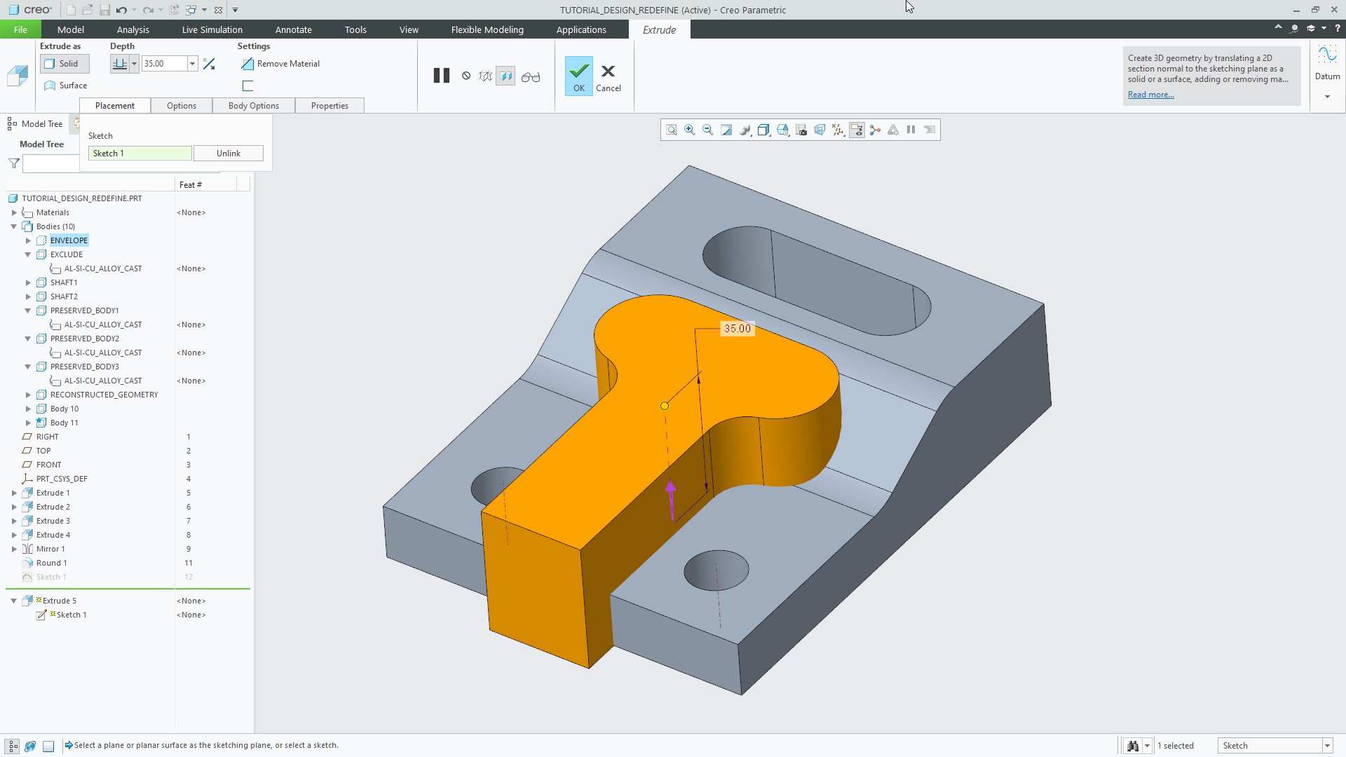
But in case you’re not familiar with the technology and technique, multibody modelling describes the ability to have more than one solid body contained in a single ‘part’ file. This isn’t a question of part versus assembly: it’s about explicit and individual chunks of geometry, embodied in a single part.
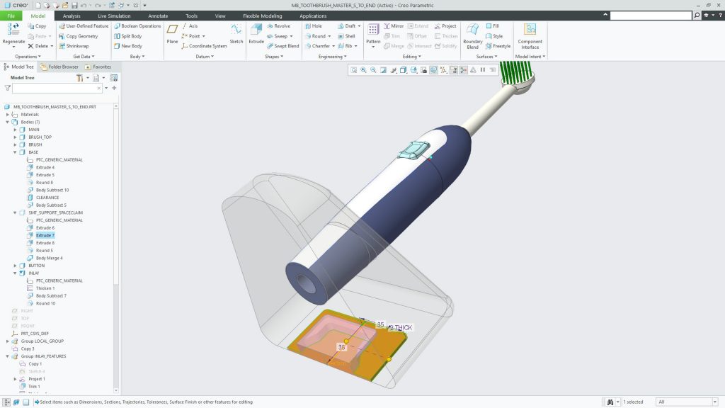
If you can achieve this, then it’s then possible to do some very interesting things. You can, for example, use a master model approach to build the exterior A surfaces of a product in one lump. Then, when the time comes, you can split them out into separate part files for further engineering.
It’s also possible to use those ‘bodies’ for other functions – such as modelling up a negative space and removing it from a whole, which might prove easier than instead trying to model the cavity.
Given the potential value here, non-Creo users might now be wondering why it has taken so long for PTC to incorporate these types of tools in Creo.
The reality is that users could probably achieve 70% of the results they needed with workarounds and fudges using surfaces and other techniques – but the extra 30% that Creo 7 now gives users is really worth the wait.
Naturally, Creo’s multibody modelling tools do all of the things you’d expect.
You can start with your first feature as per normal, then create a second, and Creo enables you to define whether new features are modifying the existing body or creating a new one.
If you then have multiple bodies, you can define whether subsequent operations apply to them all, or just select bodies as you go.
As build-up operations, each body is managed in the feature tree in terms of visibility.
While this is by no means uncharted territory for CAD users, it’s impressive that these capabilities have been so smoothly introduced into a system after nearly 30 years of development – and PTC has gone the extra mile to make its approach really unique, in several respects.
The first is that any body can be defined as a ‘construction’ body. This means it is not included in mass calculations during export, but for reference and feature-creation support only.
To my mind, every vendor that uses a multibody approach should immediately steal this idea, as it’s brilliant and solves one of the big headaches of multibody modelling.
Another is that different bodies can be assigned with different material definitions. Not only can you visualise them more easily (which in itself is not particularly unique), but you can also achieve more accurate mass calculations.
This is going to be incredibly useful for those working with master model approaches and for those developing multi-material parts (I’m thinking here of over-moulded or two-shot moulded parts and inserts, rather than additively manufactured multi-material parts).
The benefits of this will also be felt when you then follow up with documenting those individual ‘parts’ in BOMs and drawings (where hatching will differ for separate bodies).
Of course, a core update to underlying architecture like this is going to show up in a bunch of other updates to a 3D modelling system – so let’s now have a look at what else Creo 7 has to offer users.
Simulation: quick & dirty versus old-school
PTC has a long track record of providing simulation tools inside of Creo and its predecessors.
Long-term users might recall Pro/Mechanica, which was ahead of the CAD-integrated simulation trend by a substantial distance, while newer Creo users will know that Creo/Simulate has been an offering for a while now.
Alongside its home-brewed simulation tools, PTC has also partnered in recent releases with Ansys, to provide a more modern set of tools based on Ansys’s Discovery Live (ADL) simulation technology.
This, if you’ve not come across it before, is a simulation solver that takes advantage of some new methods, along with today’s ultra-efficient GPU computation capabilities, to deliver simulation results faster than we’ve ever seen before.
In other words, it might not be exactly real time, but it’s pretty damned close.
With ADL, Ansys covers not only static stress, but also internal and external fluid flow, as well as static and transient thermal studies.
The Creo-integrated version of ADL, first seen in Creo 6, saw PTC integrate the static stress and modal portions of ADL with the Creo interface and workflow.
This has now been enhanced with the Creo 7 release. In the first instance, you now have transient thermal simulation, which simulates the thermal performance of a product over time, rather than at a specific moment in time.
You can apply your starting initial temperature and gauge performance as time progresses, and handily, you can toggle between steady-state and transient thermal simulation at any time.
Another update for Creo Simulate Live is that there’s been a lot of work done to integrate this ultra-efficient, modern simulation technology with a technology set that’s been part of the Creo playbook – and its predecessors – for two decades now.
The Behavioural Modelling Extension (or BMx for short) is a set of tools that allow you to take a parametric model and use it as the basis for experimentation. We’re not talking about topology optimisation here.
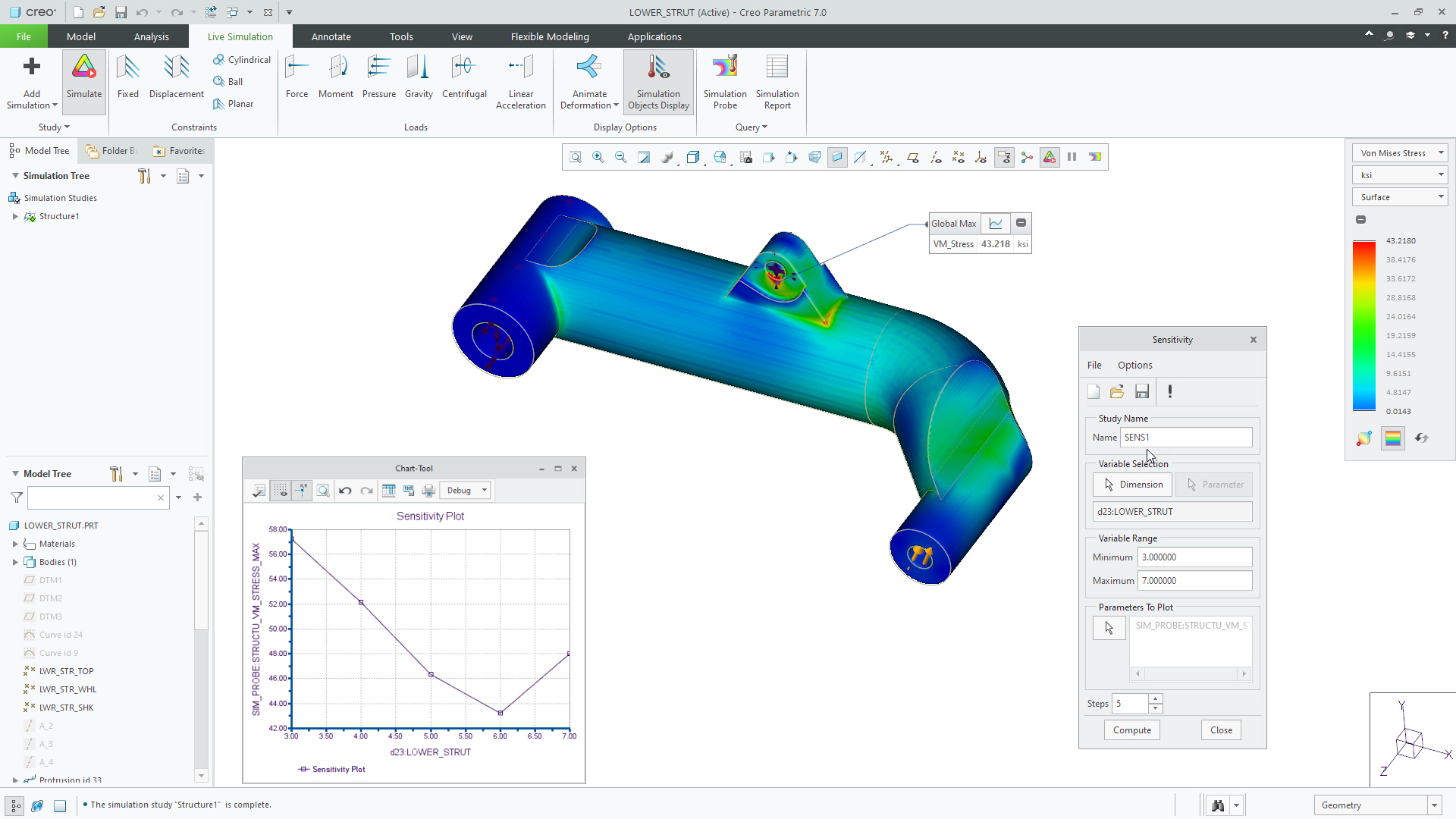
Instead, we’re referring to a much cleaner and more predictable process, which uses a number of different methods to vary parameters to reach an optimised state and meet a required goal.
That process might be an optimisation, where you vary parameters within specified limits in order to achieve a target, such as minimised mass; or it might be a feasibility study, where you vary parameters to achieve a particular property.
That property, meanwhile, could be a specific interior volume (in CPG packaging, for example, or fuel delivery in automotive) or an optimum centre of gravity for product stability.
As many will know, BMx has been available for decades, so why bring it up now?
The answer is that PTC has worked with Ansys to build a connection between Creo Simulate Live and BMx.
That’s important, because traditionally, BMx has focused on the power of parametric modelling to achieve a design goal that’s readily measurable from your CAD model (such as centre of gravity, mass, volume and so on) – and that’s very useful.
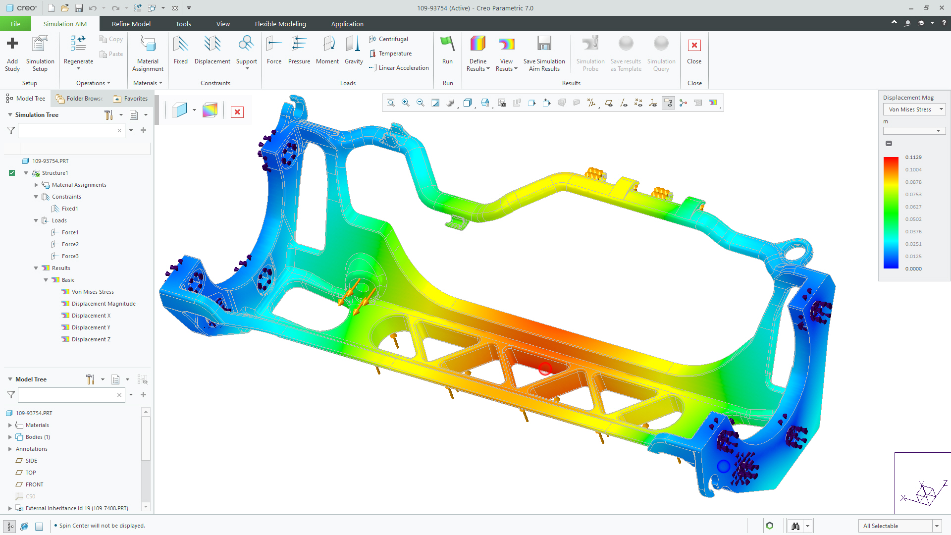
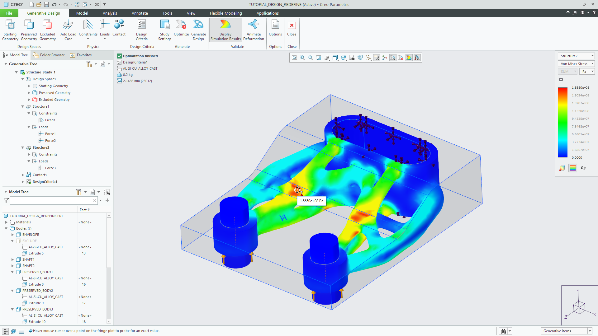
But with this new integration, you can extend this to use the output from Creo Simulate Live as the basis for experimentation, factoring in stress, strain, temperature, coefficient of drag, pressure, cooling rates, frequency response and more.
This is achieved by placing a probe and an associated measurement in the study, which can then be used to define its goals.
It’s worth noting here that Creo Simulation Live is being sold as a complete solution, so there’s no splitting out of structural, thermal, fluid flow studies and so on.
The BMx tools are a prerequisite, of course, and if you’re not using those already (the attachment rates are around 25%), it’s an additional cost.
WorkFlow: From Multi-Body Assembly Model to Generatively Optimised Parts in Creo 7

Simulation for grown-ups
Alongside the Creo Simulation Live updates, traditional simulation capability has also been a focus for this release.
Here, we see PTC start to move away from its own Pro/Mechanica technology, in favour of delivering a set of CAD-integrated tools based on Ansys’s platform.
This follows the same pattern seen with the Creo Simulation Live toolset; in other words, it’s based on using that platform directly within Creo, rather than a connection to Ansys Workbench.
The new module, Creo Ansys Simulation, offers static structural, thermal and modal simulation capabilities.
It handles meshing (using Ansys’ meshing tools) and contact in assemblies (with automation where applicable), and supports similar design of experiments to run parametric studies.
There is support, too, for more complex forms, such as beams, shells, springs and remote masses – and all using the robust and industry-proven solver technology for which Ansys is highly regarded.
For the Creo 7 release, Creo Ansys Simulation is being offered as an alternative to Creo Simulate.
‘Generative’ Design
Now, let’s consider the items we’ve talked about so far: There’s the ability to handle multiple bodies in a single part; the use of more efficient simulation technologies that take advantage of the GPU; and the enhancements around more traditional simulation tools for validation of parts.
As you may have guessed, it’s all leading to a discussion of the ‘G’ word – generative.
As you may be aware, PTC acquired generative design start-up Frustrum in late 2018. Frustrum’s focus was the common problem of using topology optimisation to solve engineering problems but ending up with a mesh-based mess of geometry.
The company’s proposed solution was to allow the user to define a study (based on required geometry, keep-out zones and so on), add multiple load cases and then have the system calculate an optimised form according to shape controls applied.
It would then return a nicely smoothed-out form that could be used to progress further. It also had a prototype geometry engine that took in new field-driven methods of geometry design for better handling of lattices and more.
This acquired technology has now started to appear inside Creo.
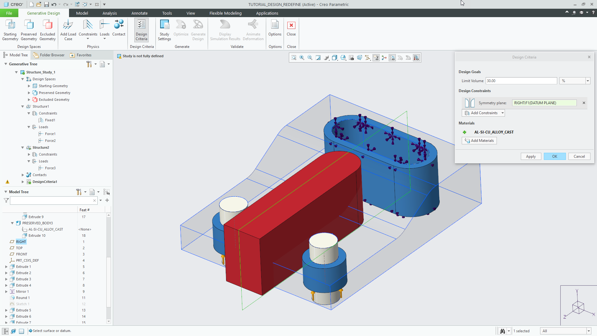
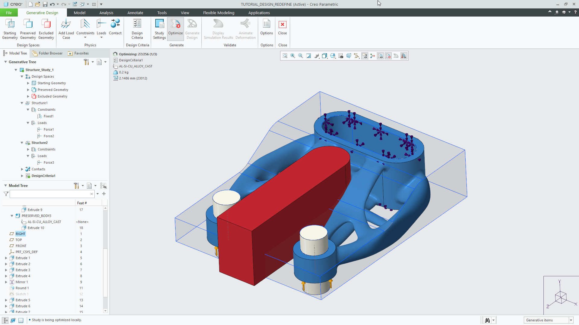
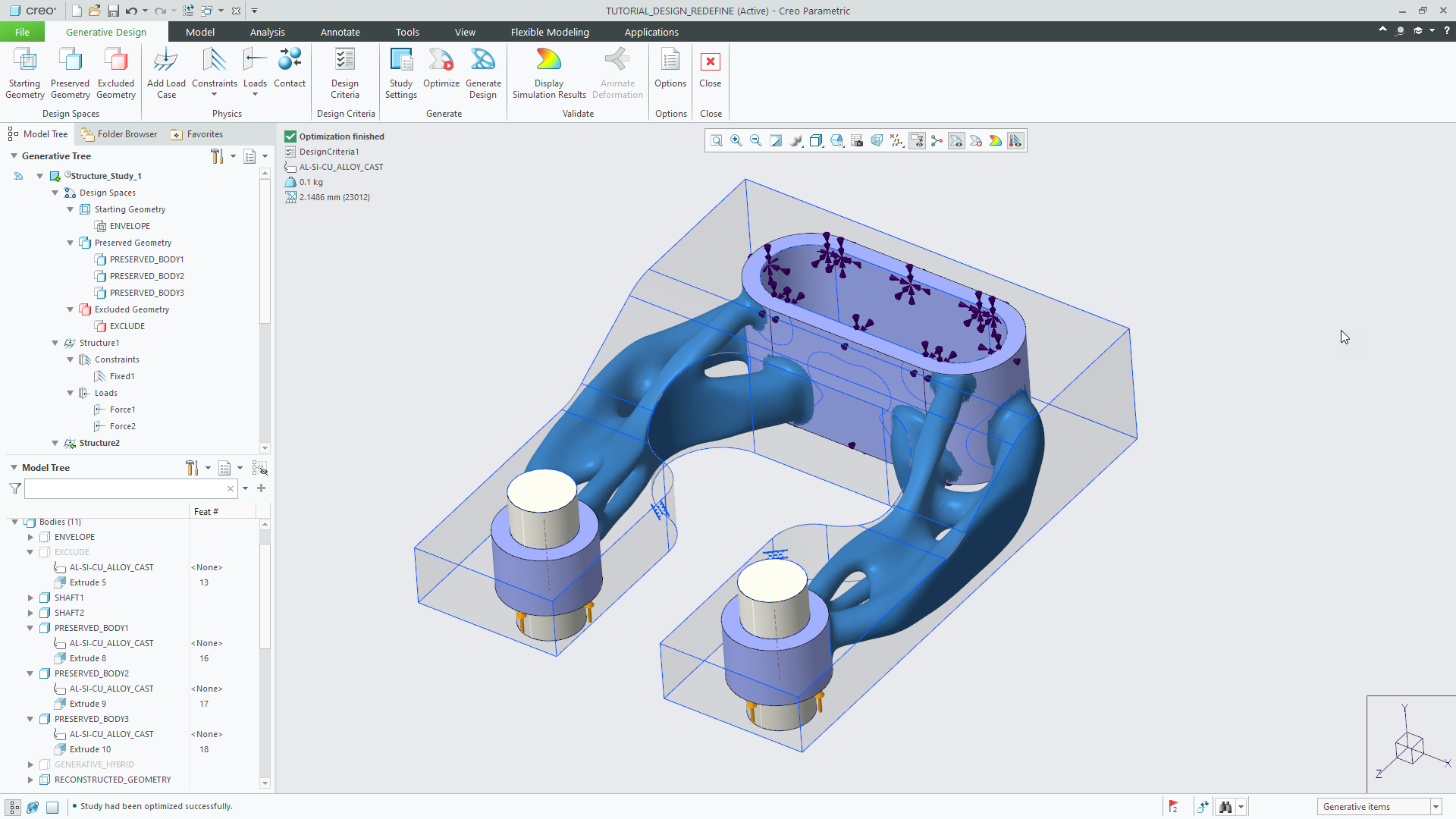
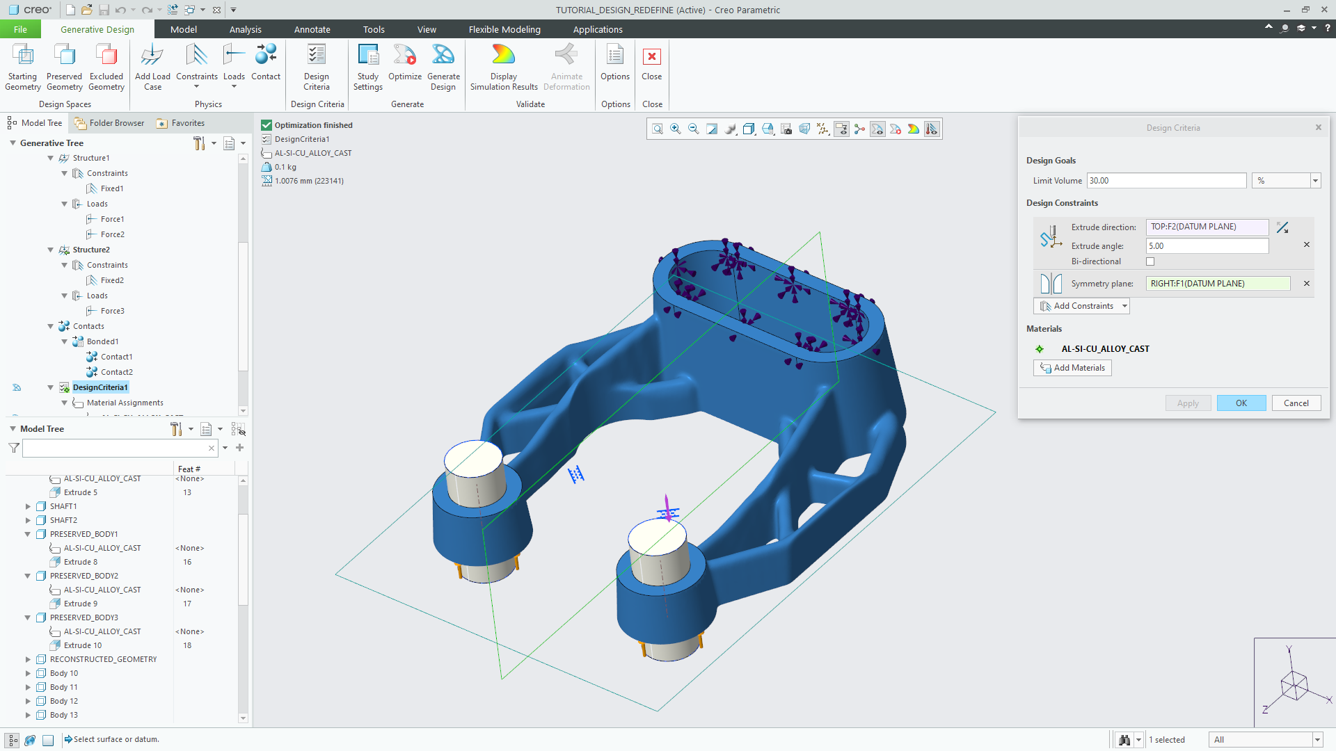
Creo 7 follows a familiar workflow: You first define your optimisation domain in terms of geometry for a starting shape, forms that need to be retained and those to be avoided.
You’ll also need to add in constraints and loading conditions, both in terms of forces, pressures and torques, as well as manufacturing-related shape controls.
This is all pretty standard for topology optimisation. What happens next, however, is absolutely not.
Frustum’s technology is highly suited to computation on the GPU and takes advantage of those processing resources to achieve something pretty spectacular.
If you’ve got a suitable Nvidia GPU in your workstation (a modern Quadro card supporting CUDA 3.5) you’ll see the optimisation start to resolve in real-time in the Creo window.
You’re not relying on the cloud, nor tying up your workstation’s processors for hours on end. It all happens in real time.
As you make edits to any of the conditions – for example, loads/constraints or geometry factors – you’ll see the results start to update in real time, too.
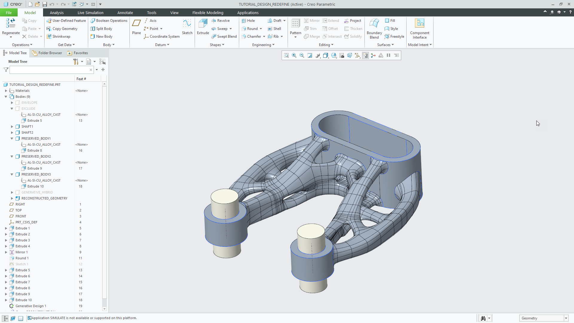
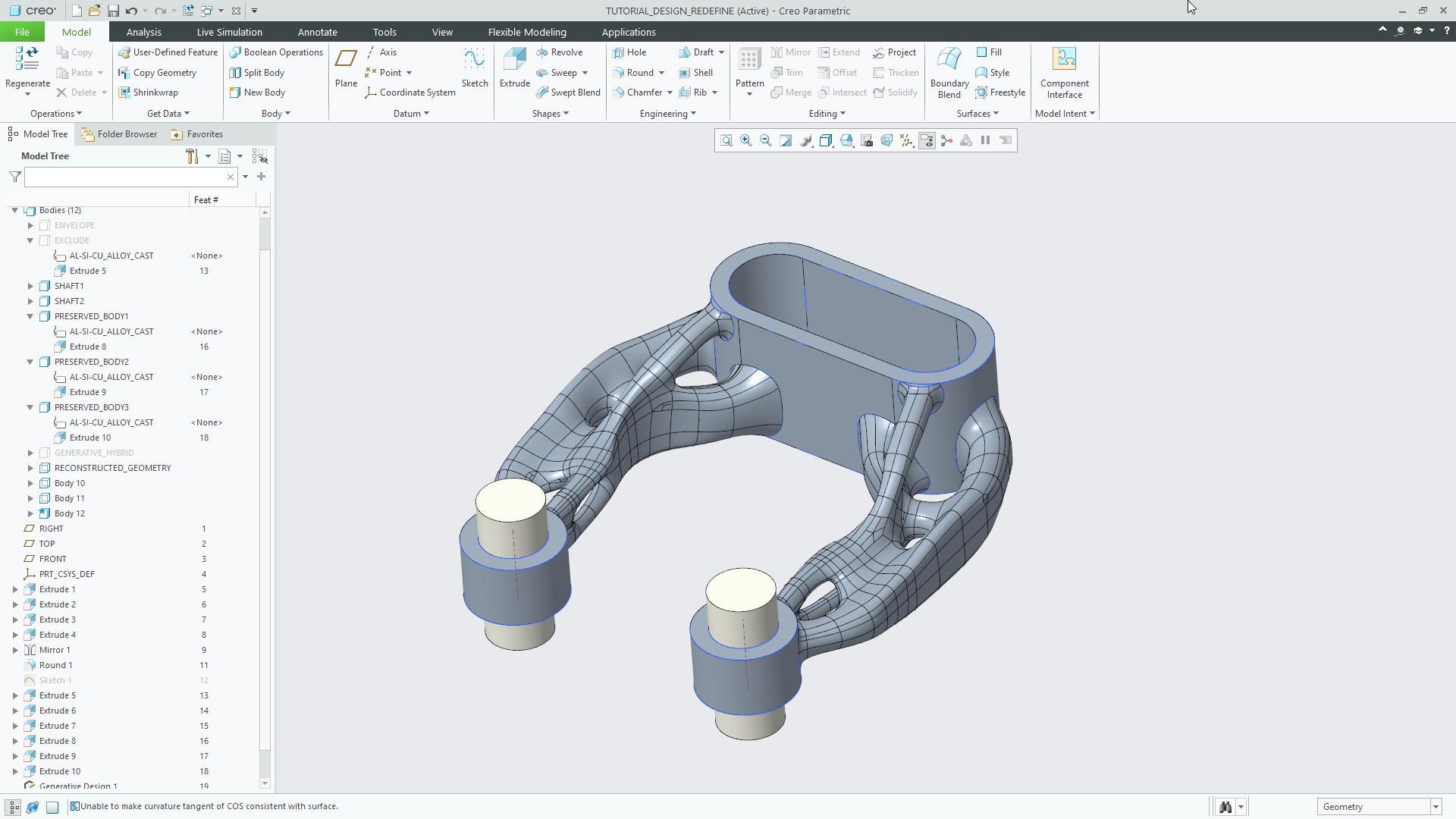
Once you have the result you want and everything has converged , you can then create a smoothed-out CAD model with a network of surfaces that can be used in downstream modelling.
Of course, there are several caveats there. Results can be highly organic and your production processes might prefer something more prismatic or you might prefer to use the results as the basis for more traditional modelling.
That organic nature might also cause issues during meshing using more traditional simulation tools.

Holistic workflow
Here’s perhaps the most impressive aspect of all of this: everything is built on a common data platform – and that means everything you define can be reused in subsequent operations and workflows.
For example, if you start with generative design boundary conditions, these can be reused to quickly conduct a more traditional parametric design study using BMx and Creo Simulate Live.
In turn, those results can be reused in a validation workflow using Creo Ansys Simulation.
The potential for some really interesting workflows to emerge from this set of tools is huge.
However, template-driven design – where an old master defines the rules and new staff create variants – comes with its own challenges.
Perhaps the biggest of these is error propagation; if you get loading conditions wrong (or just poorly defined) at an early stage, those errors will quickly creep into the rest of the workflow, resulting in a poorly designed/optimised part.
True generative design is coming
The majority of tools we’ve covered so far are coming in the first release of Creo 7, but several are billed to appear further down the line, in subsequent updates.
One of these is the traditional Creo Ansys Simulation module, billed for Creo 7.0.2 (due some time around October 2020).
Another is an extension of the generative design tools. While the tools we’ve discussed so far fall fairly and squarely into the ‘enhanced topology optimisation’ category, this newer set of tools will definitely take PTC into the realm of actual generative design.
The difference between topology optimisation and generative design is that the former focuses on reaching a single, optimum design. The latter focuses on giving you options – or optima, if you will.
Give generative design technology a set of boundary conditions, load cases, material options and manufacturing-related geometry control, and it will create a set of results that solve the engineering challenge, enabling you to evaluate, inspect, reject where appropriate and thus progress further.
Partway through the Creo release, PTC is looking to introduce a cloud-based offering that does all of this.
The claim is that it’ll allow you more freedom to explore a design challenge. As with other vendors making similar promises (Autodesk being the prime example), this is going to be a chargeable offering, but no details are currently available.
The front end, as it stands, looks in line with what you’d expect, including graphing and charting tools that are vital to filtering down larger datasets.
On the subject of larger datasets, one of the issues with this type of work is that once you start to put together larger experimental sets, the data you need to compute, then filter through, grows massively.
Given this, it’s no surprise that PTC is already talking about the use of artificial intelligence (AI) in its marketing messaging around generative design, proposing that AI will filter out those studies that aren’t needed or won’t work. How that will work in practice remains to be seen.
Visualisation & Augmented Reality
Visualisation and collaboration are two more areas of enhancement and focus for Creo 7 that I want to cover here.
Recent Creo releases have seen a number of additions for both traditional visualisation and augmented reality (AR).
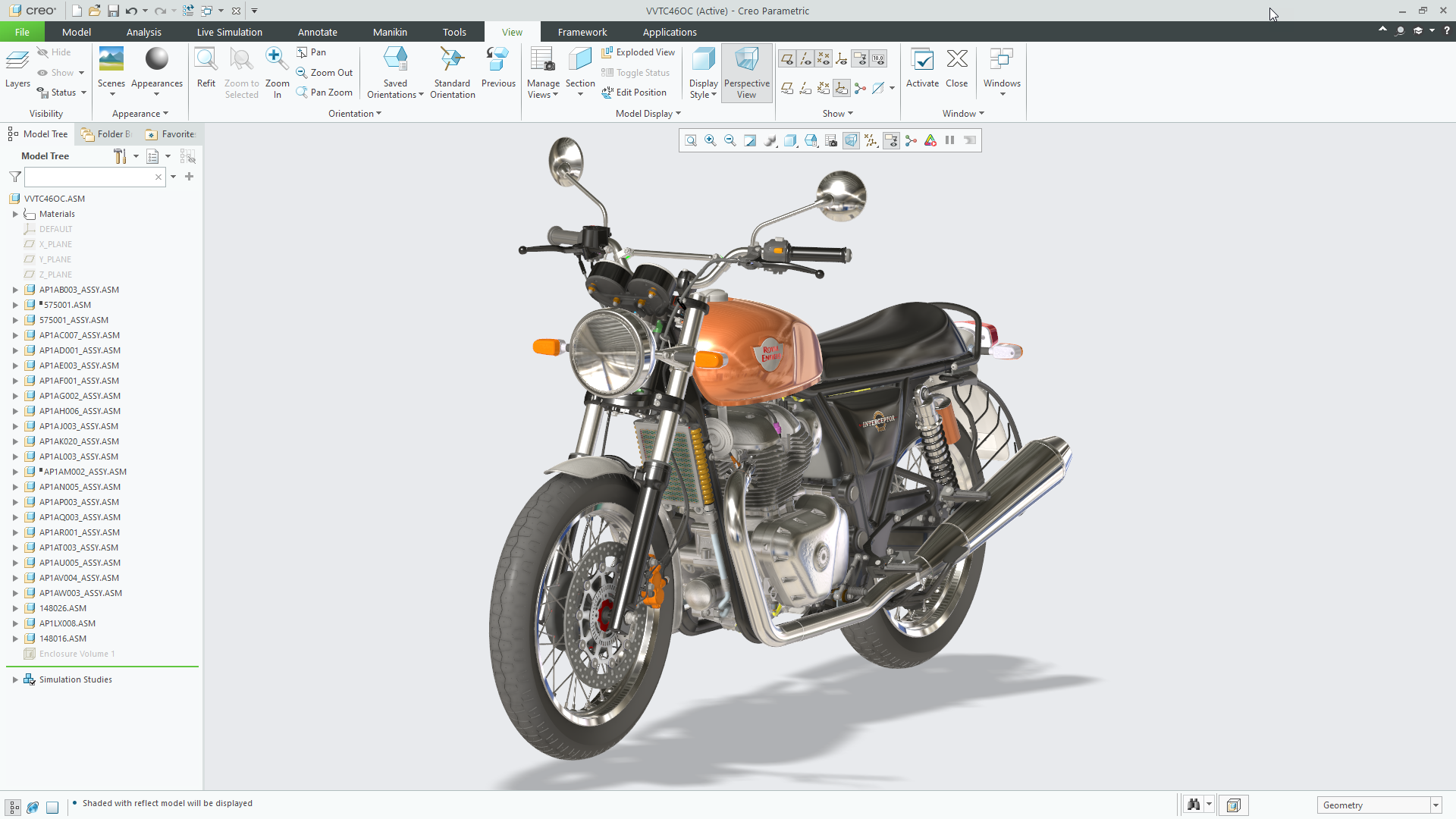
Dealing with traditional visualisation first, Creo Render Studio was introduced in Creo 5 and is built on Luxion’s rendering technology, as seen in its KeyShot product.
This enables Creo users to very quickly get an idea, directly in the Creo interface, of how their product will look, with physically based materials and realistic lighting conditions applied.
For this latest release, users can now customise the floor position in the Creo window, so that shadows can be adjusted.
Plus, if you’re using Creo Manikin, which gives your model human factors (with a full range of anthropometrics data), you can now use the ‘vision window’ to render out what the manikin sees using Render Studio.
This saves you having to fake it with a camera or other work arounds.
There’s no word yet on when (or indeed, if) Creo Render Studio will gain some of the more recent updates to KeyShot, such as GPU support and more advanced materials (such as RealCloth).
Lastly on the viz front and looking at augmented reality, PTC introduced the AR Design Share tools some time ago and have updated these pretty consistently over each release.
The most recent updates move away from a printed ‘ThingMark’ target, to an automatic location technology, which identifies a flat surface on which to place your AR object.
From Creo 7 onwards, the user will be able to publish combination states as part of an AR experience.
If you’re not familiar with Combination States, these are adapted views of your product model that could feature an exploded view, simplified representations, cross sections, zone clippings and the like, to help communicate your data more effectively.
Manufacturing: Machining & Additive
For almost all of its life, Creo has been a manufacturing focused system, as were previous incarnations.
That means there’s a substantial set of users out there who have been using this set of tools for decades and are sticking with it, from 2.5-axis through to 3-axis work, high-speed machining and into the realms of 5-axis work.
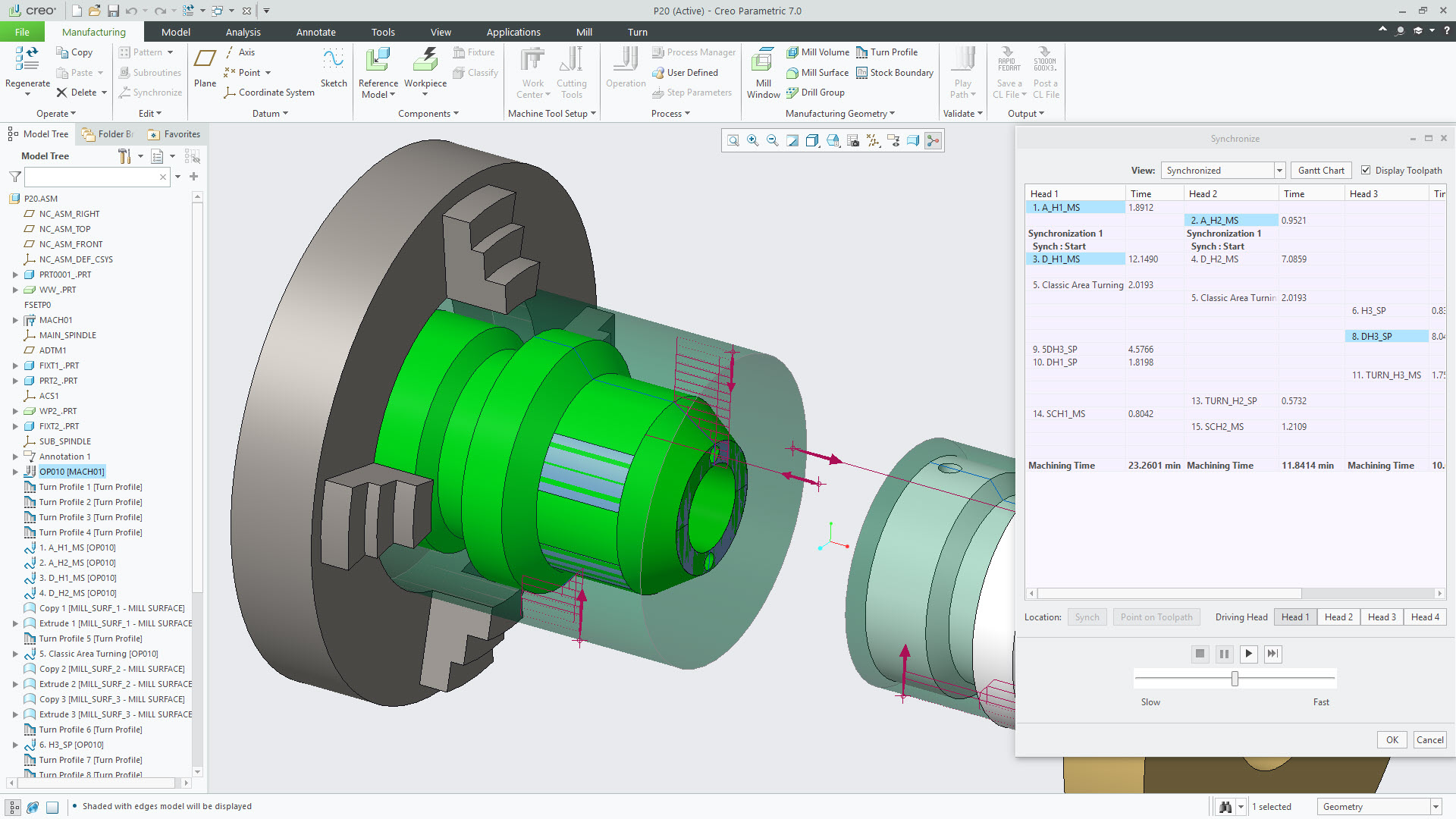
But that’s not to say that there isn’t room for some smart thinking every now and again. For example, Creo 7 brings greater support for complex multi-spindle swiss-type lathes.
Of course, the manufacturing world has also grown in recent years to include additive manufacturing as well.
While Creo has had a few updates that focus on this, the majority of tools are centred on the creation of lattice structures – and while these aren’t restricted to being additively manufactured, chances are that they will be, particularly as you move down in scale.
Creo 6 got a good chunk of lattice design tools built into it, so Creo 7 really just expands that a little to include stochastic lattices (you now have the Delauney option for how they are built).
You can now add curves and surfaces to your own custom lattice cell designs and there’s also an API-level integration to Additive Works’ Amyphon system for powder-bed fusion build simulation.
Additional updates
To round things out, let’s take a look at some smaller updates in Creo 7. These might not get much attention, but are just as important to users who go deep into particular areas of the system’s functionality.
A prime example is work done on the sketcher – one of the most used areas of any 3D modelling system.
While the functionality available in Creo’s sketcher has not changed a great deal (apart from the ability to mirror across any linear geometry), the amount of visual feedback you get has really come on.
This shows you relationships between selected parts much more clearly.
Select a line or arc, and it’ll show you the constraints that apply to it and any inter-geometry relationships, such as parallelism and perpendicularity.
Another interesting update is seen in the Freestyle toolset. This is Creo’s take on sub-divisional modelling; introduced quite a while back, it’s seen fairly widespread adoption.
A Creo 7 update to Freestyle relates to aligning surfaces with other geometry.
In addition to existing options for positional, tangency and curvature control, you can now align a surface to another using a specified angle of draft.
For those working with complex moulded parts or perhaps complex castings, this is going to prove very useful indeed in terms of cutting down on workarounds.
Other updates worth highlighting are the ability to more easily edit draft angles on imported geometry. Previously, this was a pretty convoluted workaround that required additional geometry to be built.
Now, you can use the existing draft tools, select your reference geometry and make your edits. The operation respects any associated and connected geometry, such as fillets, where possible.
The final update we’re going to cover is in the area of model-based design (MBD). This is a growing trend, particularly at organisations working in automotive, aerospace and defence.
Wherever there exists a need to fully document a part according to its manufacturing and inspection requirements, drawings are not always the ideal method to convey information.
Creo’s MDB toolset is well advanced, but Creo 7 brings support for updated standards (ISO 1101:2017 and Y14.2-2018) and new leader types for tangency, as well as a syntax checker that will not only ensure you’re able to conform to those standards, but also help ensure they are used correctly.
In conclusion
This, if I’m honest, is one of the most impressive releases of a 3D design and engineering system that I’ve seen in a good few years.
There’s a solid mix here of brand-new functionality, integrated with existing technologies, and some bold thinking around revisiting core concepts in complex product design.
The addition of multibody modelling to a system with a three-decade history may confuse a few folks – but its implementation here looks pretty damned good.
The tools are well thought out and introduce some really novel new concepts. The idea of construction bodies, in particular, is outstanding.
The integration of Frustrum’s technology is excellent. Topology optimisation is something many folks are interested in, but only a small percentage are actively using it.
There’s a rich opportunity here for users to explore what it can do for them.
Collaborative efforts with partners such as Ansys and Luxion bring best-in-class technology not just to the Creo interface, but also its underlying data platform and users’ workflows. This makes enormous sense – even if it means your licence configuration is likely to swell.
There’s much to dig into within Creo 7 and more to come as the release cycle progresses. If you’re an existing user, it’s time to start planning your adoption of new features and functions.
If you’re not, now might be a very good time to take a look.


