With Creo 8, PTC continues to successfully juggle the tasks of reinventing long-established workflows and adding brand-new tools and technologies from acquisitions and partnerships, as Al Dean reports
Over the last few releases, some interesting things have been happening with PTC’s flagship product design and engineering system, Creo. Not since the days of the move from Pro/Engineer to Wildfire have we seen this amount of investment in the core tools within the system. The overwhelming impression is of a company successfully juggling the tasks of reinventing long established workflows, and adding brand-new tools and technologies that have arrived at PTC through acquisition and partnership.
In Creo 7 and its subsequent release cycle, we saw the integration of multibody modelling with some fresh thinking on established modelling methods, as well as the integration of generative design technology from PTC’s 2018 purchase of Frustum.
We also saw the company’s partnership with Ansys continue to bear fruit. Integration with Ansys’s real-time simulation technology continues apace, in the form of Creo Simulation Live, while for those looking for traditional simulation, there’s been the release of the Creo Ansys Simulation module, which brings to Creo’s UI the Ansys Mechanical solver.
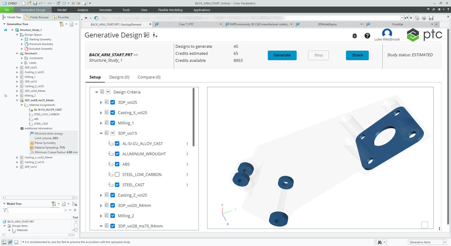
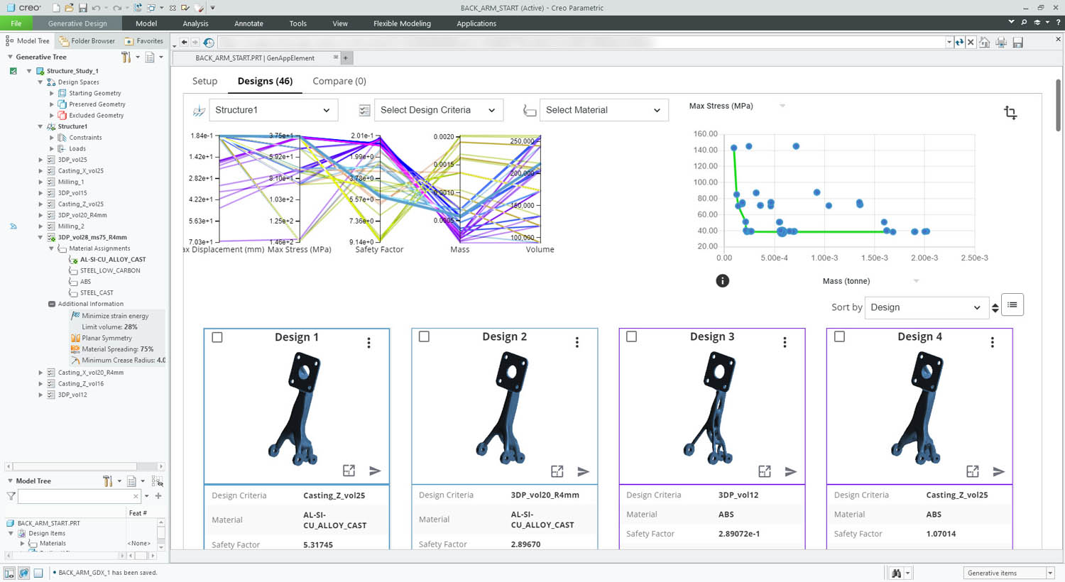
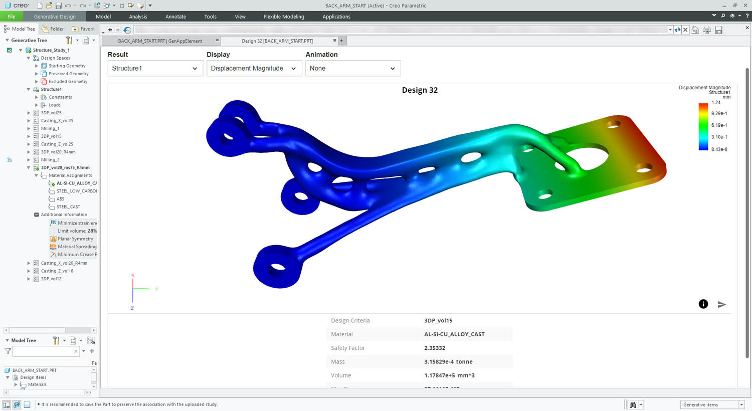
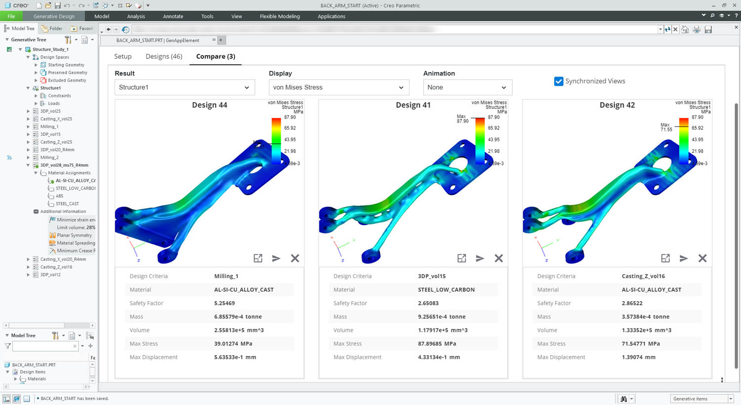
Since then, capabilities have continued to grow. A solid example is the evolution of single-goal generative design tools into a more mature form of generative design. Here, instead of using a combination of topology optimisation and some smart geometry wrangling to achieve a singular optimum, we see a ‘design of experiments’ approach and use of cloud-based compute to explore many more options for inputs (such as materials or manufacturing constraints). The result is a far broader exploration of a design space and more options at the end of it all. So, with all this in mind, shall we explore what the worldwide community of Creo can expect to see in Creo 8?
Creo 8 – Core user experience
The Creo user interface has remained pretty consistent over the last 20 years – but that’s not to say it hasn’t been consistently improved, too. For the Creo 8 release, dialogues and panels from the Creo dashboard can now be floated and docked as the user sees fit. This can be achieved on an operation-byoperation basis. The system will retain those positions and display states so your working environment stays the same.
Another change is the way in which the system displays datums. There’s some real modernisation here, in a system with a history stretching back nearly 35 years.
Finally, the user gets greater control over entity transparency for bodies, quilts and tessellated geometry, which should make working with more data clearer (no pun intended).
Alongside these seemingly minor but key improvements, there are also two new capabilities in Creo 8 that look set to impact almost every user’s workflow and efficiency.
The first is a new method of organising geometric data in part files. We’re all familiar with how a history tree is used to organise a linear progression of a part’s construction. The problem is that while the history tree is useful for understanding a relatively simple part, it can become more of a burden than a benefit with more complex parts, particularly where you’re taking advantage of multibody modelling.
It’s here that the new Design Items folder comes into play. This sits separately from the history tree, allowing you to organise your bodies and surfaces (or in Creo parlance, quilts) exactly how you want them, rather than how the system demands.
You can have nested folders and drag and drop geometric entities between them, all independently of the history tree. There’s cross highlighting, too, so selecting a part on-screen highlights it in both the model and the design item lists – and vice versa.
For a single user, this makes sense and helps organise work. If you’re working in a team, then it’s a must, particularly if that team is using complex modelling practices.
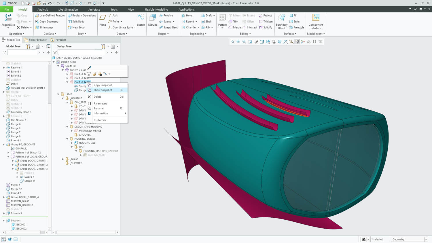
Alongside Design Items is another new feature that will change how folks work, called Snapshots. Again, this is mostly relevant to more complex practices. In particular, it’s great for situations where geometry used to build a feature will be consumed upon completion, but you still want to understand how the model was built or reuse that geometry to carry out another operation.
With Snapshots, you select the feature in question, right-click in the model tree and choose Show Snapshot. This will show you the geometry used to create that feature. On its own, this is super-useful for understanding how features are built, particularly if you’re revisiting older work or someone else’s work.
Taking things further, there’s also a Copy Snapshot command. This takes the geometry in question (the red surfaces in Figure 1 above) and copies it to the correct position in the feature tree for reuse. The link is maintained should you update the original.
Creo 8 – Product modelling
Moving on to updates and enhancements to part and assembly tools proper, the new Inseparable Assemblies functionality looks interesting, particularly for those who work with bought-in parts and subsystems. In these situations, users often want to keep the full digital definition of parts, sub-assemblies and so on, in order to ensure that mass calculations are based on accurate, material quantities. At the same time, they don’t want the headache of managing and documenting each component in that part.
By defining an assembly model as ‘inseparable’, it is classed as a single part from that point onwards. Subsequently, components can still be extracted to make them individually useful. This works as well with imported geometry as it does with native geometry.
Elsewhere, there’s been a ton of work done on holes. The system now supports wider hole types, to include NPT, PTF and ISO 7 standards, allowing a straight drilled hold to be combined with a tapered hole section. Placement of holes and use of lightweight holes is also improved. So if your part has multiple holes in a single plane, it’s now possible to very quickly define multiples in one shot. This relies on a sketch-based method, where a point is added wherever you need one.
Interestingly, there’s also an option to take advantage of line entities to achieve similar results. For example, if you sketch a line, it’s possible to have the system add a hole at both the end point vertices and/or the mid-point.
While these updates focus on creating complex hole definitions as quickly as possible, it might also be the case that your part has hundreds of holes and isn’t the most efficient part on the planet to hold in memory.
To get around this, it’s possible to switch to lightweight/graphics-only representations, which should make manipulation much more efficient. (This was available before, but has now been expanded to include tapered holes and more.)
Other notable improvements include added support for slots in PCB import processes; support for tape and stiff shrink fit fittings on harnesses and wire routing; the ability in sheet metal to create multiple flanges off a set of curves in a single step (including mitre and corner relief where needed); plus, there’s a new curve type added, in the form of a geodesic that finds the shortest distance between two points over a surface.
Creo 8 -Documentation & MBD (Model-Based-Definition)
Whether you call it model-based definition (MBD), product and manufacturing information (PMI) or 3D annotation, the use of a 3D model as the host for the geometric dimensioning and tolerancing (GD&T) that’s an essential precursor to the production process is gaining ground as an idea.
In some quarters, it’s an idea that’s being adopted. While the traditional 2D drawing isn’t going away, many organisations are looking for new ways to work and, in some cases, consolidate their intellectual property as 3D models.
PTC has been ahead of the MBD curve for quite some time, pouncing on it before many of its competitors. That headstart shows up in the maturity of the tools on offer. While other software companies are still trying to get their houses in order to support these processes, PTC is already tackling some of their nuances and finer points, ensuing that users who choose to go down to this path have the tools they need.
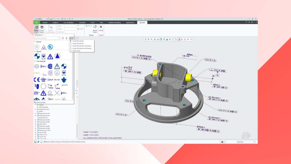
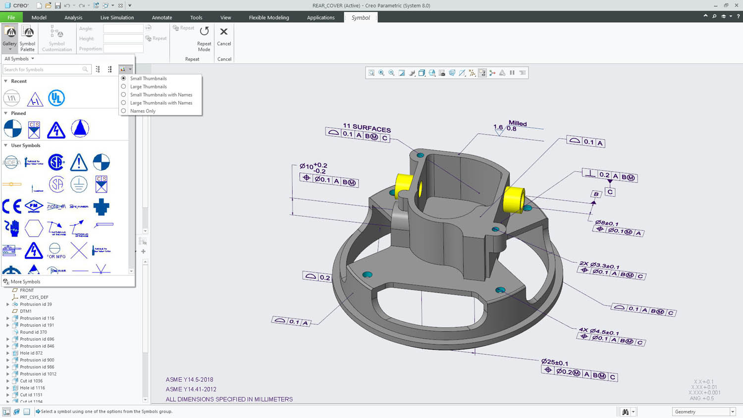
Evidence of this shows up in the new symbol gallery, which contains all of the standards and industry specific symbols you might need, along with the newly streamlined placement and editing workflow.
Take, for example, weld symbols; where once you might have defined a weld symbol and attached it to the appropriate set of geometric features to define a weld in situ, you can now create the data when you create the weld feature which automatically populate into the annotation. This means all of your data is centralised more effectively.
Then there’s the way the PTC team has reworked surface collection – the process by which you select the faces on a part you want to annotate. There are now many more options for automatic face selection (tangency, by loop, and so on), saving you the trouble of having to do this manually.
Lastly on the MBD front, the GD&T Advisor introduced in Creo 7 has proven useful for those users who are new to MBD and old hands alike. It’s an active system that checks your applied annotations to ensure that they’re consistent and fully defined. It’ll identify where annotations are incomplete or inconsistently defined, or where geometry has been edited during design changes and references are out of date as a result.
You can just dive in and fix those annotations while the system’s running, so it’s much more interactive than a simple syntax checker. For Creo 8, this has been updated to support assemblies as well as just parts.
Before we step away from documentation of design and engineering, I also wanted to touch on something that’s new in the drawing environment too. It relates to managing legacy drawings that, for one reason or another, are not connected to a 3D model. As we’re all aware, one of the benefits of the ‘3D model to 2D drawing’ approach is that each view is generated from the model, maintaining inherent associations with the source model and to other views on a drawing sheet.
If you’ve got a drawing that is disconnected from a 3D model, or which was hand-drawn originally, that relationship between different orthographic views does not exist. Well, there are now tools that allow you to redefine views within a legacy drawing and add that intelligence back in.
Simulation and generative design
While Creo 6, 7 and subsequent inter-release updates have hugely expanded the simulation offerings available in Creo, this release sees those tools gain even more capability across the board.
For example, in the case of the real-time Creo Simulation Live (based, as we’ve discussed, on Ansys’s Discovery Live technology), the Creo integration gains steady state fluid flow capabilities to compliment the transient state capabilities already present. In fact, steady state has become the default!
On the subject of Simulation Live, the system also includes probes to get specific data from specific points of interest in a model. The issue in the past was that, once defined, these could not be adjusted. It was a case of deleting and recreating them. Now, they can be edited in situ, saving you a bit of time when adjusting a model and simulation.
On the Creo Ansys Simulation front, which sees the Ansys Mechanical solver integrated into the Creo interface, the bulk of the work was done between the initial Creo 7 release and now. But there was clearly still room for some improvement, particularly in the area of mesh control.
A mesh control setting is now made available to the user and edited through the simulation tree, as you do with all other simulation related items, inputs and outputs. There is also additional mesh diagnostics feedback from the process manager – which will help you troubleshoot any issues more quickly.
Lastly, the licensing of this module is a little more seamless, so Creo will automatically pull a licence when the tools are started up, rather than requiring the user to explicitly obtain one.
Moving on from more traditional forms of simulation and into the brave ‘new’ (well, 20 years old) world of generative design, the integration of Frustrum’s technology continues.
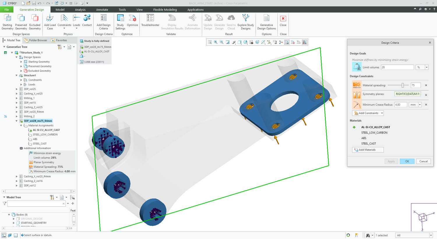
As with many such tools, the core workflow here is to define loads and constraints (both geometric, in the form of features required and keep-out areas); material definitions; shape control (to guide a solution towards being suitable for particular manufacturing processes); and, typically, a design domain.
The issue here is that while the user might be aware of the first three items, the design domain can be tricky. If you get it wrong, you could steer your optimisation study in the wrong direction entirely.
To make this easier, Creo 8 introduces a tool to take stock of your defined constraints, then work out the most suitable design domain automatically. Of course, you can still dive in and define your own domain, but this will get you there quickly.
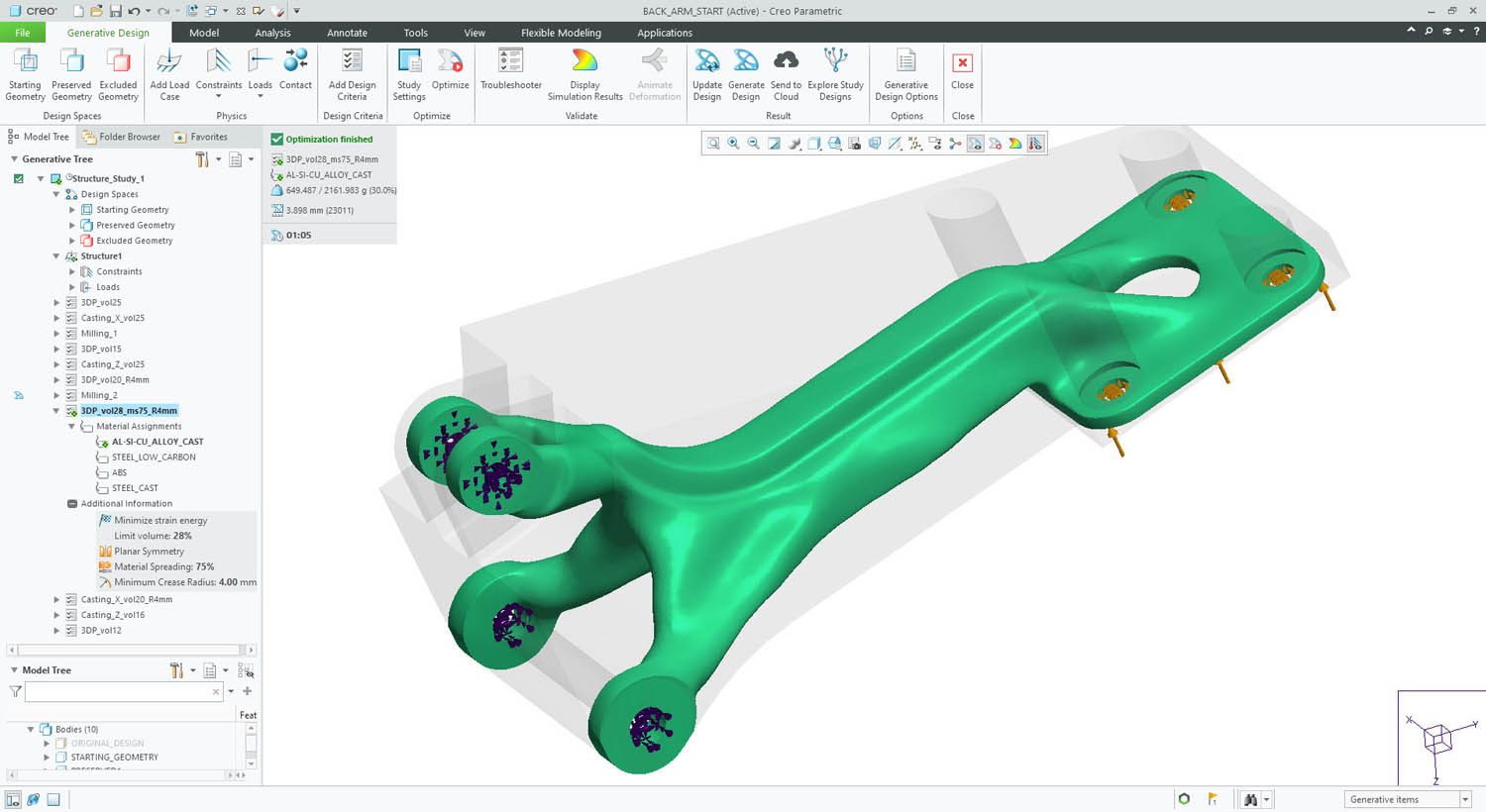
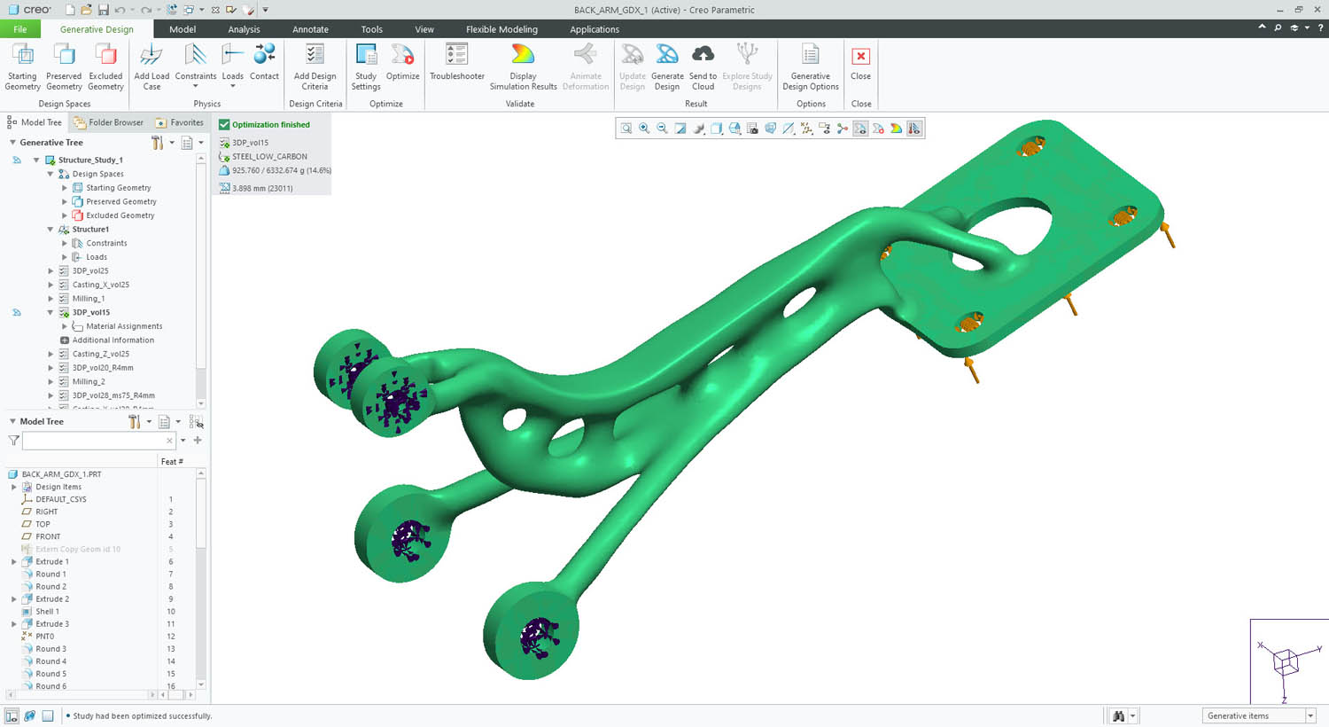
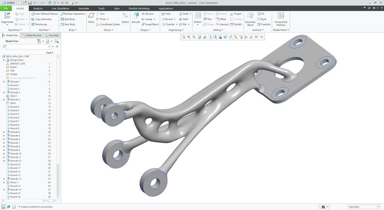
Elsewhere in the Generative Design Extension, there’s been work done on geometry reconstruction – something that’s a strong point of Frustum’s tech, in that it can give you very smooth, near-productionready surfaces.
For Creo 8, these have been improved, particularly when working with a ‘casting’ geometry constraint. Now, parting curves and draft angles defined in the optimisation process will be maintained and used to drive the reconstruction of the geometry in Creo.
There’s a new option to control the smoothness of the final shapes – specifically, to ensure that a minimum crease radius is respected. This should reduce the stress/strain concentrators that can often arise from topology optimisation-based processes.
Finally, for generative design and on a local computation front, it’s now possible to run optimisations asynchronously.
Previously, you’d lose access to Creo while a run completed, but now you can start off an optimisation to run in the background and work on another dataset at the same time. The Process Manager schedules tasks running in the background then sends you a notification when they’ve completed.
Creo 8 – Machining & AM
From its earliest days, PTC has always had a presence in the CAM and CNC programming world. Things got a bit of a boost a few years ago (around Creo 5), when the company acquired libraries from Machining Strategist. This brought its CAM tools up to more modern standards, particularly on the high-speed machining front in the 3-axis world. For Creo 8, this has been expanded to support 5-axis operations for both roughing and automatic deburring.
There’s also some interesting work around taking existing toolpaths and converting them into 5-axis operations, in order to help with both reach and when working with shorter tooling.
On top of this, you’ll also find new 3+2 capabilities introduced to roughing and rest roughing, if that’s your bag.
Moving away from machining and onto the hot topic of recent times: additive manufacturing (AM).
No release these days can pass without the ‘A word’ coming up. It seems like every vendor is trying to shoehorn in the tools that support the creation of parts using 3D printing techniques, irrespective of their actual use in the field.
That said, PTC offers a set of AM tools that’s better than most. The last few releases have seen latticing tools added into the system for lightweighting and the development of more structured parts/ materials.
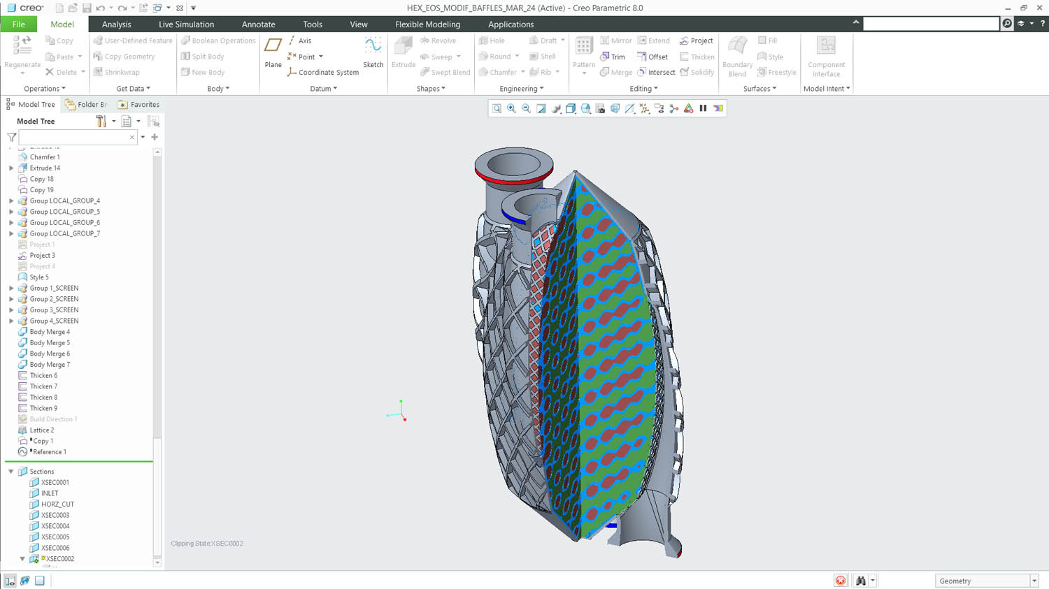
For the Creo 8 release, this work continues with a focus on two key areas: simulation driven lattices and formulabased lattice structures, with some tweaks and additions to how these are created.
The tweaks to formula-driven lattices allow you not only to create the solid portion within a gyroid lattice (commonly used in heat transference and radiation applications), but also the negative space.
This of course means that you’re able to conduct fluid and heat simulation tasks to validate your work more easily.
The simulation-driven design work, however, is where things get really interesting.
It works like this. Carry out a stress analysis run on your product, using the tools at hand. Once done, take either the results file (from Creo Simulate) or a set of probe points (From Creo Simulation Live) and use these as the basis for varying either thickness of the beams in a uniform lattice, or the density of lattice with uniform beam size within your part at the point where the simulation tells you it is required. Higher stress equals more support.
Of course, the simulation is based on a solid, uniform block. Replacing that with a variable lattice is going to need some iteration to find the right balance.
Finally on the AM side of things, there has also been some work done on tidying up lattices; specifically, the removal of any ‘dangling beams’, where a lattice’s elements do not complete a triangulation and just hang out in free space. These can quite easily cause issues in the build process.
In conclusion
We also looked at Creo this time last year. Back then, our feeling was that PTC’s big focus was on extending partnerships (particularly with Ansys), building brandnew tools and technologies, and not being afraid to revisit existing tools and workflows and improve them.
I’m happy to report that there’s been little deviation from this three-pronged strategy – and that’s 100% a good thing.
Once again, we’ve seen the partnership with Ansys bearing fruit and extending Creo’s simulation capabilities. This applies to both the real-time Simulation Live tools and the more traditional tools, and now extends to including the Ansys Mechanical solvers directly in the Creo interface.
If you’re going to partner with a simulation vendor and take advantage of its knowledge and capabilities, Ansys is a pretty solid bet, right?
Alongside this, the extension of newer tools such as design for additive and generative design show there’s a good opportunity for Creo users to experiment not just with new ways of creating designed and engineered forms, but also to optimise those forms and more traditional parts for new methods of production. The perfect example here is the ability to generate the negative space in gyroid forms.
Then we get to the updates and rework of the core modelling tools. These are perhaps my favourites. Generating a simulation-driven lattice that needs to be additively manufactured is one thing, but if you can give a whole community of users tools that let them all get their work done in a more efficient manner, that’s a much more far-reaching benefit.
The new abilities that enable users to quickly take a peek at how a model was built and reuse geometry without needing to recreate it, or to organise their geometry data structure to make it easily understandable for themselves and others are examples of not being afraid to revisit age-old workflows.
PTC should be applauded for it – and more vendors should think about adopting that approach themselves.
Exploring design alternatives: Creo & cloud computation