SolidWorks has been on the market for over 15 years. While it didn’t rewrite how things were done on a technology front to start with (it was essentially Pro/Engineer on a more affordable platform), it’s grown consistently over that time to define how mainstream 3D design and engineering tools are not only sold, but used.
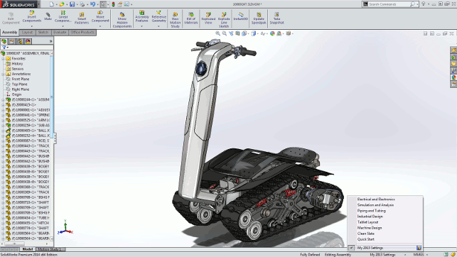
Environments allow not only standardisation and customisation, but also come with a bunch of industry specific pre-sets
Today, there are two million licenses out there, half a million of which are in a commercial environment, and the rest in education.
In the last few years, to keep pace with the maturing CAD industry, SolidWorks has introduced new features into its system and refined existing tools. It’s also enhanced workflows and expanded its offering, including simulation.
User experience
Let’s start with a look at some of the changes to how the user interacts with the system in general.
SolidWorks hasn’t had a major user interface (UI) overhaul for quite a few years but, there are a few key updates in this release. They are varied, so let’s look at the big items.
Perhaps the most interesting is the introduction of ‘environments’. An environment in a UI context is a preset for the user interface and controls which toolbars, property managers and such are shown.
Alongside the ‘quick start’ beginners environment, SolidWorks also has a set of pre-defined settings to match perceived industry workflows. These include industrial design, electrical or electronics, machine design, pipe and tube design as well as simulation and analysis.
Alongside this, it’s possible to have the system use your previous environment set-up stored and restored from my.solidworks.com (the community resource introduced earlier this year) as well as to create and store custom environments with preferences for toolbars visibility, shortcuts, commands, menus, mouse gestures etc.
For the experienced user, it’s useful to have a consistent look and feel across different machines, but for those looking to get new staff on-board or if the system’s being used within an academic environment, the ability to reset the UI to a standard layout will be invaluable.
Another globally applicable update is the ability to control equations at the configuration level. In older versions, equations could only be suppressed, however now it’s possible to define variations of equations and global variables, and apply them to individual configurations.
There is something else worth noting that will prove useful even for advanced and experienced users. Now recently edited features can be accessed from a folder in the property manager. These entities can be selected by a lasso which, when combined with the selection filters, lets you grab geometry quickly and efficiently.
Tools for industrial design
While SolidWorks has always been strong in machine design, it’s also found a home right at the heart of industrial design.
Assembly counts might not be as high, but the complexity involved in creating clean, smooth and aesthetically pleasing surfaces requires a different set of tools.
For the first time in a while, SolidWorks has paid a lot of attention to this area and it’s worth looking at a few of these tools on their own.
An excellent starting point is one for those who prefer sketching (manual or digital) for ideation and concept capture — that’s pretty much everyone, right?
We’re all familiar with using sketches as the basis for laying out curves and surfaces, but the problem is often that the images imported (either from a digital sketch or a scanned manual one) are the wrong size.
There’s a new tool called Sketch Picture Scale, which enables you to pick out reference points, add in dimensions and the system will then scale the image precisely to match. It’s been in industrial design tools like Alias for some time, but it’ll be useful for SolidWorks users in the consumer products field.
The new Style Spline is worth a good look too. This tool is added alongside the existing spline operation, but adds in a set of tools that gives it much more usability within the creation of smooth, consistent and aesthetically pleasing surfaces. After all, the base sketches are fundamental to achieving clean surfaces.
This new operation allows geometry constraints (including the new path length constraint we’ll cover shortly) whether that’s tangency, curvature continuity or anything else — without all of the faff usually associated with defining these with the existing tools.
Its definition follows the method usually found in bespoke industrial design applications (like Alias and Rhino) and allows you to have curvature combs to enable evaluation as you sketch and modify control point positions.
There’s also been work done on building out the conics tools introduced in the 2013 release.
Assembly design
Mechanism design has always been a strong point for any of the mid-range modelling systems and SolidWorks is no different.
While its toolset is mature and advanced, there’s always room for some new tricks and capabilities. The first is that there’s a new addition to the mechanical mates list. The new slot mate allows the ability to constrain components as they would in a slot (see below image for an idea).
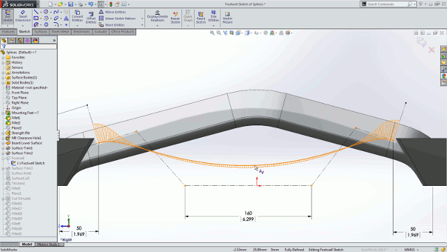
The new Style Spline gives greater control over all aspects of its geometry
Interestingly, the user has control over how the parts can move. It’ll limit movement to the slot automatically, but the mate can also be locked to a specific point, either a percentage along it, to a mid-point or to a fixed distance.
The second is that when laying out belts and chain profiles, it’s now possible to add in a specific value for a path. This allows users to experiment with positions of drive and pulley components while ensuring that specific component sizes are adhered to and accommodated.
Thirdly, and on the more generally applicable assembly design front, there’s now more control over section views. Not only in terms of performance, but also the added ability to include or exclude specific components from the section.
This will make inspecting and, later on, documenting complex assemblies easier for most users. Finally on the assembly front, there’s been a small addition to the exploded view creation tools that now allows parts to be rotated as well as translated/moved.
Specialised offerings
SolidWorks has always been sold as a general purpose tool that’s just as applicable to the industrial design crowd as it is to those working in the machinery design sector.
That said, there’s alwaysroom to add in specialised functions or product offerings that extend such a general offering into niche areas. SolidWorks introduced two of these in the past year or so, focussing on the Electrical and Plastic part design industries.
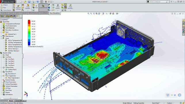
Thermal properties and PCB layout can be directly reused in SolidWorks’ Flow Simulation tools
SolidWorks Electrical: This looks to solve the complexity and data issues associated with electrical and mechanical design.
Whether that’s defining schematics in 2D, reusing the same data in a 3D environment, harnessing and routing design or using standard parts (there’s half a million included within the system).
It’s all there in a single package that combines SolidWorks’ existing tools with specialism from the ElecWorks add-on.
SolidWorks Plastics: Introduced in 2013, SolidWorks Plastics brings together a set of tools explicitly aimed at the design of injection moulded components.
It combines SolidWorks and its inherent power at modelling such forms with the injection moulding simulation tools from SimpoeWorks.
Since Dassault Systèmes acquired that company earlier this year, it’s clear that there’s been a greater amount of integration, which leads nicely onto simulation in general.
SolidWorks simulation
Simulation has been a core part of SolidWorks’ offering for many years and the available toolset is pretty rich.
From your bog standard static analysis into CFD, fatigue and dynamic assembly analysis. It’s all there, albeit as a cost option.
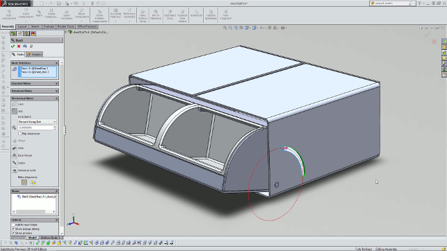
The new Slot mate provides intelligent mating conditions that allow a mechanism to be tested while allowing them to be locked when needed
The SolidWorks team has always done a pretty solid job of enabling the user to take design data and quickly repurpose it for analysis.
Connectors have been the standard method of doing much of this work — encapsulating standard engineering connections (think welds, springs etc) in a much easier to use form than what traditionally has been the case with simulation tools.
This release sees work done on how the system translates Toolbox fasteners and associated features defined in the design environment and reuses that data to set-up bolted connections for use in simulation studies. It works in linear static, non-linear static, and non-linear dynamic studies.
Similarly, it’s also now possible to reuse data from the other areas of the system in simulation. The first example is the ability to take reuse thermal properties and PCB definition from electrical components and use them to set up flow simulation.
Secondly, if using SolidWorks Plastics and its moulding simulation tools, the residual stresses and temperature data from the injection moulding process can be used to conduct further studies on their impact on the part’s performance in SolidWorks Simulation.
Elsewhere on the simulation front, there’s a new capability that will prove useful for those working with configurations to solve iterative design problems. It’s now possible to use the Result compare tools, which allow inspection of four sets of results at the same time, across configurations in the same model.
Conclusion
SolidWorks is a beast of a system. Taking a step back and looking at it as a whole, it’s quickly apparent that everything’s there.
From fundamental part, assembly and drawing tools, into niche areas such as rules-based design, pipe/tube and harness. There’s also now more specialism with the likes of SolidWorks Plastics.
What 2014 represents is an evolution of that technology mass. There’s no single item that makes this a stand out release, but there’s finesse added into many workflows, processes and toolsets.
A perfect example is the new Style Spline. This doesn’t replace the existing tools (it can’t, in fact, for legacy issues), but it now brings more control and usability to a key area for many users.
Another is the integration work between the design and engineering definition tools and the simulation technology. Across the board, the company has looked at where data can be reused, saving time and reducing many of the assumptions associated with simulation study set-up.
Whether it’s the ability to pull residual stresses from an injection moulding simulation into stress analysis or extracting thermal properties from electronics components for flow/heat analysis, they all combine to improve data reuse and work together to give a much clearer picture of how a product will perform in the real world.
The end result, for the 2014 release, is a system that evolves the existing tools, adds in some specialist tools where needed, enhances workflows and builds efficiency into an already highly powerful and capable system.
I think most existing users will find something in here that either makes their daily working practices more efficient or allows them to be more productive.
| Product | SolidWorks 2014 |
|---|---|
| Company name | DS SolidWorks |
| Price | $995 |


