
Engineers and designers often consider complex engineering simulations to be beyond their capbaility but here, in the first of a series of simulation workshops, Laurence Marks shows how a multi-physics problem can be solved using generally available CAD tools such as Abaqus
In this first article we look at a multi-physics scenario that features moving parts and the non-linear response of a flexible component to fluid dynamics. In simple terms, it’s a seal that gives up when the pressure of the fluid gets too much for it.
The aim is to find out why it is giving up and how this can be solved.
Geometry
In this model {fig. 1} the geometry has purposefully been kept simple.
The basic parts need no further discussion as they are just solid CAD parts. However, with regards to the fluid – any region that can have fluid in it at any point is also considered as a part.
The solver needs to know where the fluid starts off – so another part is defined which defines the position of the water at the time the simulation starts.
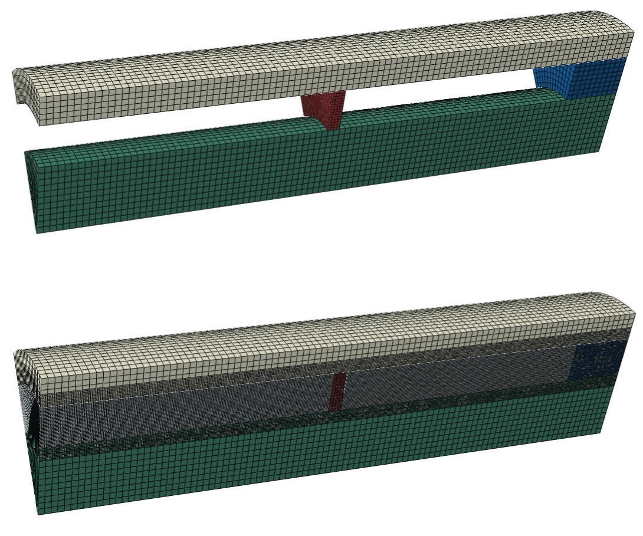
The user might note that a single sector has been modelled to speed up the solution process – the software allows the results to be copied round the central axis.
This is good for meetings if you don’t want to explain that if a problem is symmetrical, only a section needs to be modelled {fig. 2}.
Coupled Eulerian Lagrangian
The solution technique chosen for this problem is Coupled Eulerian Lagrangian (CEL), which combines two well known simulation approaches.

Eulerian where what we are interested in travels through a stationary mesh, like the fluid in a CFD (computational fluid dynamic) model, and the Lagrangian approach where the mesh travels with the deforming parts, like an FEA (finite element analysis) model.
In our model {fig. 1} the fluid moves through the Eulerian mesh and the solid material moves with the finite element mesh. The solver then tracks where the fluid can flow and where it can’t, depending on if there’s something solid in the way.
There’s some clever stuff going on with regards to modelling the surface of the fluid; where it’s free to move as it wishes or where it impacts on a solid.
Model set-up
As well as meshing the solid parts, the fluid domain has to be meshed too {fig. 3}.
Once this is done the relationships between the parts is defined. This “all with self” general contact handles all the complex interactions – in some respects it’s what you pay for when buying a code.
Setting the initial position of the fluid is done by selecting the solid which has been drawn for this purpose. Simple. So all that remains is to set up the definitions of how the solid parts move (or don’t). This is done using pretty traditional simulation displacement boundary conditions.
The model is now solved. Although the model is simple to set up, the solution isn’t instant; depending on the hardware available it takes several hours to solve. It’s worth noting that multiprocessor machines really speed this sort of thing up.
What the model shows
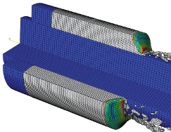
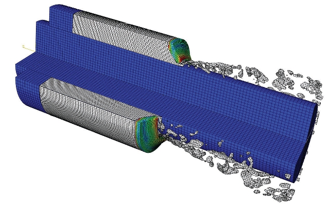
As the piston moves to compress the fluid, pressure builds up on the seal.
The seal initially resists the pressure, but as the pressure increases further the free edge which contacts the central rod moves, releasing fluid. As we are using a fluid-structure interaction (FSI) approach we can track the fluid movement past the seal {fig. 4}.

This means that not only do we have a prediction of the pressure at which the seal will blow, but also how it will behave when it does – even down to the spray pattern that develops as the fluid and structural dynamics interact.
If we are trying to develop the art and science of this sort of thing, then this is the critically important design tool.
So, this simulation shows how a multi-physics problem can be solved in a sensible timeframe.
Perhaps that’s the secret – trying to encapsulate the essence of the design problem and solving it in a manner that provides useful design data. After all, isn’t that what engineering simulation is all about?


