nTopology Element – There’s a new focus on the use of lattice structures in engineering forms but both defining and designing these forms is a complex field. We look at a system that is specialising in taking the complexity out of the process
There’s a growing movement that’s exploring the potential of lattice structures in the engineering world. While much of this is driven by the rise of more sophisticated additive manufacturing processes, it’s by no means restricted to it.
The reason that lattices have become a focal point is that they provide a way of improving engineering performance whilst allowing the user to strip mass out of a part.

nTopology’s Element allows you to work with geometry to create ultra lightweight, efficient forms
Mass, of course, means energy. Energy to produce the part, energy to move the part. Less energy means lower costs and more efficient structures.
And, although the benefits of lattice structures have long been established, the problem has always been that fabricating them has been incredibly difficult. This is where additive manufacturing comes into play as it has the potential to manufacture these forms with less difficulty (let’s be clear, growing a part with lasers and titanium powder is by no means “easy”).
There is also the issue that traditional CAD systems struggle when it comes to lattice forms. Yes, you’ll see some start to introduce latticing functions (Creo and NX have introduced such tools recently), but once you get past the ‘swap out some solid geometry for a recurring pattern’, you hit a performance brick wall.
This is where nTopology comes in.
Founded by Bradley Rothenberg in 2015, the company is developing its Element system, which is focussed on the creation of lattice structures to solve a wide range of engineering challenges, in an efficient manner.
At present, nTopology Element doesn’t have any geometry design tools in the traditional sense, so a form is required as a starting point. As you might expect, this is typically modelled up in a more traditional CAD system then exported to nTopology Element, using STEP, IGES or Parasolid data format.
The system will also import a mesh via STL or OBJ, but, personally, I’d prefer to start with analytic geometry then use Element’s meshing tools where needed.
It’s key to note that while there are tools available to extract data (in terms of reference faces) inside nTopology Element, if you’re looking to optimise specific portions of your design, you might want to consider splitting these into separate bodies or parts before you export. Once you’ve done that, open up Element and import your starting geometry.
The workflow for nTopology Element is unlike traditional CAD tools. After all, we’re working with very different forms and very different parameters for the design of parts. The goal here is to allow you to develop the lattice structure so that it’s present where needed, in the form needed.
nTopology Element in use
We’re going to run through a pretty simple project to give you a flavour of how nTopology Element works, using a brake lever. Here, the loads and boundary conditions are well known.
We’re aware of where and how it’s constrained and where the basic forces act.
A lattice in nTopology Element is made of up of nodes and beams within a 3D space. Its goal is to create these in the shape that you want, as a very simple geometric element (similar to using beam modelling in FEA). This keeps things light and efficient, only creating more complex geometry when needed.
There are a wealth of options for lattices in nTopology Element, both in terms of cell type (the geometry that’s repeated to build up the design space) and how it’s constructed.
They can be built from a single surface, between two surfaces (think sandwich panels), to cover just the surface of a set of geometry or to fill that geometry entirely.
Your selection of the lattice type and how it’s constructed will depend entirely on your application. nTopology has built Element so that you’re dealing with very lightweight, functional representations of your eventual mesh. As you start to build up your lattice, you’ll see it represented on screen as a mid-beam element. This means you can fine tune, adapt and edit your lattice in a very efficient manner.
While the system focusses on automatic generation of these forms, it also includes a wide range of more manual editing tools, whether that’s to clean up the lattice, add in or remove beams where needed, adjust nodes to tweak the lattice or to merge separate forms together.
All of the Edit tools are found under the Edit toolbar and will allow you the finite control you’ll need.
Once your lattice or lattices are in place as lightweight models, it’s time to turn our attention to turning these into thickened geometry. But, before we do, it’s worth exploring what modifiers do, as they have a heavy influence on the next part of the process.
nTopology Element – modifiers are key
When developing a lattice, you have a couple of options on how to guide both the form of your lattice and the thickness of each individual beam across your part.
To guide this, you need to create Modifiers. These will control two aspects. The first and most widely applicable is the use of modifiers to vary the thickness of each beam in your lattice — adding more thickness where stresses focus.
The second is using modifiers to guide the size of the lattice cell across the form. As the latter is a lesser used function, we’ll focus on the former.
These modifiers can be added into the system manually or using imported FEA result data. To create them manually, you have three types to choose from: point, vector or surface.
Point will allow you to add a point (or series of) to the model. You choose the position, then define its range of influence as a spherical radius outward from that point. You can also adapt how that range influences thickness with a drop off graph.
Vector modifiers are only really used in a couple of instances to drive lattice build variables using a vector in a specific direction.
Surface is perhaps the most useful modifier as it allows you to select a surface (or group of connected surfaces) to use as the driving point for lattice thickness variation. These surfaces can be imported as part of the initial import, as a separate import, or can be created after the fact, using the Extract operation.
While the manual modifiers allow you to dive in and use your engineering knowledge to make a best guess, another approach is to take advantage of stress analysis tools to find exactly where your lattice needs to be beefed up.
Element is starting to gain some stress analysis tools of its own and can also connect up with SimSolid or import data from Abaqus. The built-in stress analysis tools allow you to conduct a basic linear static study on your part to find out where stress focal points are.
They’re pretty basic in the current form, but it saves working with another system and the usual fun and games that go with exporting and importing data.
nTopology Element – adding meat to the bones
At this point in the workflow, we now have the lattice defined as a lightweight beam model that we’ve finessed into the correct form. We also have modifiers generated to guide where we need more material in the eventual part. So let’s crack on.
In the first instance, you’re able to create a uniform thickness lattice, which is pretty trivial to do. Load up the Thicken operation, select the lattice, add your thickness value and you’re done.
Where things get complicated is when it comes to using a modifier to generate a more complex lattice. Here, you need to ID the lattice model, the modifier and add in your values for the minimum and maximum thickness. This is then combined with the range information from your modifier and applied across the lattice.
There’s also the ability to have a number of different lattices present in the same project. This means you can define multiple thickening values for each, handle them separately, then combine them when you need to.
nTopology Element – tidying up your parts
The final stage of the part design process is less about generating complex forms and more about tidying them up to ensure that the resulting lattice-based part fulfills requirements.
One of the major issues here is that while the lattice can be designed inside a structural volume, you’ll find that the thickening operations will grow the lattice outside of this volume.
In some instances, this might be acceptable but in others, you might want to use the originating geometry to trim back your lattice to give you a clean, efficient engineered form.
The Utility menu in nTopology Element is where you’ll find these tools and it’s worth spending some time with them as they’ll let you do more interesting things with your parts.
One example that comes to mind is a part that has a variable thickness lattice but also features a number of required engineering features. Using a variable thicken operation, it’s possible to over thicken around the required features.

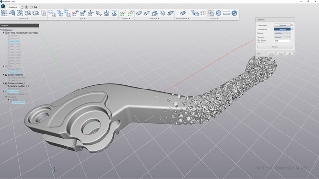
A variable thickness stochastic lattice used to lightweight a pretty standard component and ensure that the engineering features are retained where needed, but reducing mass where allowable
This will blow out the lattice, but a simple Boolean with the original geometry will trim things back nicely and give you solid geometry where you need it. The image above demonstrates how we’ve got the engineering features near the pivot end and the lattice emerging into the part in the other end.
Exporting your parts
Of course, the final stage is exporting your component — whether that’s getting it additively manufactured, using the data for a casting pattern or, indeed, importing it into a more mainstream CAD system for inclusion in further engineering work.
After all, we’re creating lattice structures that are lightweight, efficient and easily usable in a wide range of engineering disciplines, from the micro structures needed for medical implants to using the same set of tools and design parameters to scheme out a roof canopy.
At present, Element includes three export options. The most commonly used, I suspect, is the old school STL or OBJ export.
To create these, you need to mesh the part. This is a complex process in many cases, with potentially massive facet counts. Handily, Element includes tools to help you mesh, refine and reduce your mesh where needed in order to get it to a useful size, without compromising on the fidelity of the results.
The second option is a CAD export (available in the Pro version). This uses the thicken model to send proper CAD geometry to a STEP file, though, again, these are going to pretty hefty in size. And, with CAD systems increasingly adding in the ability to work more efficiently with mesh data, will be needed less and less.
The last option is to generate a LTCX file, which is essentially a recipe to rebuild the lattice in the receiving system.

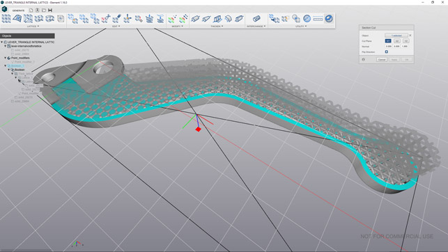
There are the basic inspection tools you’d need — measurement and sectioning — but no thickness analysis which might be useful
In conclusion
nTopology is amongst a handful of startups exploring the potential for a different breed of design that takes advantage of new ways of manufacturing parts.
While we have already seen traditional CAD vendors attempt to shoehorn lattice design tools into their existing solutions, the reality is that traditional CAD systems aren’t the ideal place to explore this new world, and are unlikely to provide truly efficient and effective tools.
Element is in its first release and there are still aspects of the system that need to be fleshed out. Such as easier selection of geometry (particularly in the analysis tools) and a greater attention to the learning aspects of the system (although additional tutorials and a more in-depth help system is in the works).
That said, it’s perfectly possible to dive into the system and experiment freely to see where you can get to — and this is absolutely fundamental.
Lattice design is something that very few of us have ever been trained in or even considered, but the reality is that it’s worth exploring both in general terms, but also in specific reference to projects we have underway.
Now that we have the methods of manufacturing these types of forms (both using additive as well as more traditional casting methods), we need to explore how to design them and find out what sort of benefits we can derive. To do that will require a lot of learning, a lot of experimentation and a lot of iteration — all of which Element enables very well.
nTopology has two products — Element Free is, as you might guess, free with some limitations. The Pro version adds another layer of import and export, automation, with greater control over your lattices and post processing tools.
If you’re curious about lattice design, I would encourage you to download the Free version and see what you can do.
The software is easy to figure out and it’ll be even easier to figure out with the forthcoming help system.
nTopology has built a remarkable system that looks to be unique in an emerging market that soon may become critical to many in the near future.
What’s key is that it’s eschewed some of the common conventions of how engineering is done with geometry. It’s built a system that makes the use of these incredibly useful forms more efficient by focussing development on a set of tools that allow the user to experiment, refine and learn, rather than trying to make it fit into an existing CAD system.
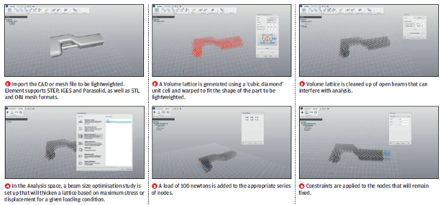
Workflow: Using Element to lightweight a part with nTopology’s Element system
nTopology Element is a powerful design tool for creating complex geometry for engineering applications. One of Element’s best strengths is its ability to lightweight parts quickly and efficiently.
This workflow is a step-by-step process showing how to do just that. From preparing models, creating and modifying lattice structures and optimising structures with analysis tools, this guide shows the different workflows and capabilities Element provides to engineers.
The part being optimised is an aerospace component under consistent and heavy load. The goal of this redesign is to generate a part that offers significant weight reduction that can still withstand a high loading condition with a minimum factor of safety.
Due to design constraints, the shape of the part needs to be maintained and connection geometry for pins needs to be preserved.
Through lattice structures, optimisation and analysis with the system, a volume reduction of 60 per cent is achieved while the stress is more efficiently distributed over the whole part compared to the original.
| Product | Element |
|---|---|
| Company name | nTopology |
| Price | On request |


