

Since the acquisition of Delcam by Autodesk a couple of years ago, the development team behind the high-end manufacturing products have been working on bringing the various products together in a more cohesive manner, starting with the user experience in 2018. This addresses an issue that has been a potential barrier to wider spread adoption amongst the manufacturing community.
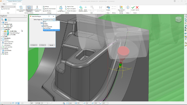
The new PowerShape 2018 UI showing how you can adapt tool angle where you need to — without recomputation of the entire operation
The products (PowerMill, PowerShape and PowerInspect) each grew out of a drive to provide the most suitable environment for their focus areas, the end result was a set of software products that had only a vague consistency in terms of user experience.
Each with their own way of working and individual approaches to carrying out common tasks.
While that’s not an issue if you’re working with just one of those tools, if you’re swapping between, for example, PowerShape to wrangle your geometry into a workable core and cavity, then switching to PowerMill to work through those key operations, any differences, even the slightest, make for a less than optimal experience.
There has also been the simple fact that while existing users have grown up and matured with these products, the user interface (UI) styling isn’t what today’s users have come to expect.
Consistent user experience
While we’ll get onto the functionality updates for the 2018 release cycle shortly, the biggest item we need to talk about is how the UI across all of the products is changing.
As you might expect, from 2018, all of the Power Solutions tools are receiving a makeover at a very core level as Autodesk is bringing the Ribbon style UI across the board. While its use varies with each product, there are, of course, common aspects across the whole product line.
You’ll find all of the commonly used tools (view control, shading, etc.) are in the same place and have the same icons in all products. When you dive into the functionality within each one, you’ll notice grouping by operation or focal point.
In the case of PowerMill, you’ll see the workflow broken down by tab, from stock set-up and datum creation, through operation definition. You’ll also see a range of additional tabs for the less used operations and commands. The same is true for PowerShape and PowerInspect — typically workflows are the order of the day and it makes a lot of sense.
What’s interesting is that the team has taken this opportunity to also expose a lot of functionality that might typically have been hidden away in more obscure menus and dialogs.
In the case of PowerMill, a good example is the control you have over how tool-paths are structured (in terms of the number of points on a curve etc.), which would have been very difficult to find in previous releases.
Of course, if you’re an existing user, this may cause some initial confusion and require a period of relearning. PowerMill is the type of system that can be heavily modified, perhaps to reduce the onscreen clutter or to expose just those operations used daily.
The good news is that any customisations made can be carried across to the new UI and when combined with the standardised interface’s customisation tools (to create your own tabs etc.), should get you up and running again.
Now that we’ve covered the new user interface (and existing users have cleaned up the coffee from the magazine), shall we take a look at the more functional, machining related updates to this release of PowerMill?
Functional updates
PowerMill is a curious beast. Its reputation was born from its development and subsequent adoption for the mould and die industry.
That reputation has been built up over the last 20 or so years based on a couple of things. One of which is that the system is tuned for dealing with the complex forms found in the mould and die industry. Deep cavities, a need for high quality surface finishes and the drive to use the most advanced machine tools on the market.
This moved from, now standard, highspeed machining strategies, through wider spread adoption of both positional and simultaneous five axis machining methods — mixing in more advanced tools like on machine verifi cation (OMV) along the way.
Machining of mould cavities is a hardcore business. Anything that gets you to that final set of operations quicker and gets the mould into production will be of interest to many. This has been part of PowerMill’s strength for a good many years.
One of the most unique things about PowerMill is its ability to edit toolpaths.
Toolpath editing
Not in terms of each operation (all CAM systems do this, obviously), but at a much more granular level — and do so without needing to recompute the entire toolpath.
While for simple parts, this doesn’t seem like a big thing, for the types of surface machining we’re talking about here, the ability to edit individual passes or the connection between those passes is rare.
And it has been part of PowerMill’s unique selling point for a decade or more. But that’s not to say that there’s not room for improvement.
In the 2017 release, the ability to dive in and adapt the angle of cutter approach in fi ve axis toolpaths was added. This allows you to compute an operation, use PowerMill’s built-in machine verification tools, find areas of collision and manually adapt the tool-head and cutter’s alignment by rotating the cutter and toolhead within the machine’s movement.
Click the cutter, invoke the operation and you use an on-screen triad to position the cutter and head to the position you want. The system then recomputed that portion of the toolpath in its entirety.
For 2018, this has been extended to allow much more localised edits.
Essentially, you can find areas that need tweaking, select them (using a variety of selection methods), adapt the tool angle and the system handles the rest; adapting the transitions between those toolpaths (to ease machine movement) is handled automatically, as is the recomputation of those areas.
This also means that if you have a complex feature to machine, you can assign your cutter alignment angles to each face and have the system work out the best transition between those adjacent faces, quickly and easily.
This editability doesn’t end with cutter approach angles either. The 2018 release also introduces the ability to do the same for feed rates for surface groups. It allows you to define different feed rates for a surface group and the system handles the transition between them.
While you might want a ‘global’ feed rate set for a part, machine and material combination, there might be instances where you want to slow the machine down to machine certain features — most typically, around thin wall sections, whether that’s on the tip of a blade in the power generation market or around thin walls in cavities or, indeed, electrodes.
While this has its uses in three axis machining (particularly with high-speed machines and full flute cutting), it’ll really come into play with more complex five axis work, as the combination of smaller cutter tip movement combined with large head movement around curved, thin features (think; the tip of an aerofoil) could cause surface quality issues.
This lets you spot those areas and slow things down as you need to — in a single operation, rather than breaking it up into separate operations.
This is backed up with a new diagnostic shading method which colour codes your toolpaths by feed rate, so you can see the end results more clearly, rather than relying on a purely numerical display.
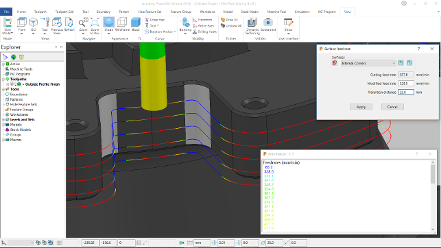
The new feed rate control tools are backed up with automatic transition handling and a new diagnostic display mode to help visualise how your part will machine
Stock simulation (Viewmill)
While we’re talking about simulation of machine tools, it’s also worth noting the updates to stock simulation for 2018.
While PowerMill’s Viewmill has been the stock simulation method, this had two modes. One which gave you a higher quality display of your current stock model during machining, but lacked the ability to rotate or zoom in. The other gave you a more dynamic view, but at a lower level of quality.
As you can imagine, these two have now been combined, meaning you have a single view model that provides a rich display of stock while allowing you to pan, zoom and rotate the model.
Elsewhere in this area, PowerMill also provides much more feedback about areas where rapid moves are straight into stock, potential collisions or crashes during simulation — of course, working either to finite collision or if you don’t want to fly by the seat of your pants, to within a specific clearance distance.
These are fed to an onscreen dialog allowing you to snap between that list and the graphics windows, so you can see what’s going on. While generally useful to everyone, when it comes to five axis work and full machine simulation, it’ll pay real dividends.
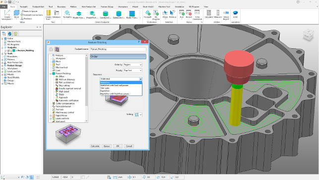
3D offset finishing
3D offset finishing enables the machining of complex surfaces using a boundary or chain edge as the basis for a toolpath that offsets inwards from that boundary.
While this proves useful when combined with a ball nose cutter, there could be instances where the final toolpaths didn’t quite clear up the remaining stock — meaning manual finishing or a secondary pass in that area.
To solve this, the 2018 release adds a centre line pass to the end of the operation to clear up that last bit of remaining stock.
2D machining and turning
Alongside the updates and improvements to 3D surface machining, the last few PowerMill releases have also seen the product break new ground in terms of adding technology for both 2D machining operations and the introduction of turning capabilities.
The 2D machining is a realisation that PowerMill’s customers also have to carry out this type of work as part of the mould production process and would prefer to use the same tool they’ve already invested in.
Meanwhile, the addition of turning is to enable the use of mill/turn machines, for the same reasons.
In terms of 2D machining updates, the existing toolset is pretty standard, but gets some new tricks courtesy of technology elsewhere in the Autodesk machining portfolio.
One such update is the ability to create a ‘top fillet’ toolpath that allows you to machine 2D style bosses, but also incorporate a fillet at the top edges without requiring an additional operation — whether that’s done with a ball nose or a special purpose fillet cutter. Another update is the ability to cut sidewalls and bottoms of pockets with a single toolpath. Previously, this would have required two separate operations.
Lastly, there’s been an extension of toolpath simulation and collision avoidance, with the system now checking 2D operations against not only the cutter and tool-holder, but also any remaining stock on the model.
On the turning side, there have been a few key updates that afford the user more control over not what can be turned, but rather how it is done. A prime example is the greater control you now have over the order in turning operations — these can now be limited, reversed, divided or reordered as you see fit — again, without having to recompute the whole toolpath.
Another key update for turning in PowerMill is the addition of greater collision checking, which now moves beyond the workpeice and the cutter to include the machine, tool assembly, workpeice as well as fixtures and stock.
PowerMill’s 2D machining capabilities are growing with each release — now allowing you to machine sidewalls and the bottoms of pockets in a single feature, as well as a new operation for machining top edge fillets
In conclusion
There are small scale updates across all of the tools within PowerMill for this release, but we’ve highlighted the key ones applicable to most.
Some of these other updates are industry specific, such as the ability to reuse the operations designed for blisk and impeller machining in other situations. But, ultimately, this release is all about the user interface, particularly for existing users.
Autodesk has done the job properly, I’d say but with a caveat. I’m a firm believer that not everything needs to conform to the Microsoft style ribbon UI guidelines — after all, we’re doing complex work, not jockeying a spreadsheet.
This has always been my thought with regards to PowerShape and PowerMill.
The types of workflows and processes are complex and involved. That said, there are instances where forcing an established user community to relearn many of their daily work practices makes sense.
Ultimately, the move to the new UI has been made; Autodesk has used a pretty well considered approach to the design of the new UI and it’ll make the range of systems much more accessible to both new and existing users. Those time served users will no doubt have some readjusting to do, but I would expect this to be in the region of days, rather than weeks.
The reward being more accessible software, particularly useful for those looking to push the boundaries of what they can do, rather than simply rinse and repeat variations of the same programming jobs.
In terms of updates to the functionality, it’s good to finally see some greater cross pollination of technology between these various tools (as well as other connected tools such as FeatureCAM). Autodesk now has a huge amount of manufacturing knowledge in-house and a large scale set of technology to back it up. By reducing duplication of effort across these teams, you get more thought out workflows and quicker implementation of new technology or ideas.
In terms of cost, the bundling of the various systems here has been greatly simplified. As with all things Autodesk now, the products are available on subscription only. If you’re an existing customer on maintenance, then nothing changes for now, you still get all of the updates and new tools.
To give you an idea of how PowerMill breaks down, you have three tiers of product — PowerMill Standard, Premium and Ultimate. The Standard bundle covers high-speed three axis, 3+2 (or positional five axis) machining, 2.5D and turning and machine simulation. It’s also restricted to neutral file format import (STEP, IGES etc). That starts at £2,095 per quarter.
The Premium bundle adds native file import (including Catia and NX), full five axis programming, automatic collision avoidance and offline robot programming and costs £3,145 per quarter.
Ultimate includes all the above plus electrodes, blade milling, blisk and impeller manufacture and ports and manifolds – coming in at £3,840 per quarter.
Those costs vary depending on whether you go for a monthly, quarterly or annual renewal of your subscription — it’s worth noting that it also includes phone support and any subsequent updates during your subscription.
Finally, this release is the first time that there’s been trials available for PowerMill.
Each of the products we’ve talked about are now available for 30 day trial of the highest level of bundle. There are some restrictions, such as PowerMill only allowing post processing of three axis toolpaths, but it’ll let you get a feel for how the systems work.
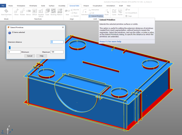
PowerShape 2018 allows you to quickly extend all surfaces resultant from reverse engineering a laser scan, enabling quick trimming
Beyond PowerMill: Updates to PowerShape & PowerInspect
While PowerMill is definitely the jewel in the former Delcam crown, the product range has some serious capability to it, in the form of both PowerShape and PowerInspect.
Both products have also seen attention in terms of the holistic user experience and, again, the new UI is slick and well thought out — tailored to each system’s workflow and typical user case. That said, there’s been work done on the functionality in both PowerShape and PowerInspect which is worthy of note.
PowerShape 2018
PowerShape’s tribrid modelling approach has been through something of a renaissance of late. In addition to being able to wrangle not only surfaces, solids and mesh data into shape, the system also started to gain more intelligent modelling tools with the introduction of the Parasolid kernel a few years ago.
2018 continues this with the addition of new sketching intelligence that allows you to not only sketch parametrically and associatively, but to also drive those dimension constraints as you would in most other modelling systems. It might be hugely useful for most PowerShape users, but for those looking to build intelligent and adaptable models (perhaps of standard fixtures, stock etc.), then it’ll be ideal.
Also, PowerShape’s ability to work with mesh data alongside solids and surfaces is something that has predated more mainstream tools, which are currently making a lot of noise about it.
In this release, the tools continue to mature with not only greater control over selection (using more intuitive methods), but also a new automated mesh fixing tool.
This follows the conventions of the existing “Solid Doctor” tool in PowerShape, that applies a set of preconfigured checks and fixes to surfaces, but adapts it for mesh repair. Again, you have the same ability to step out of this wizard driven workflow at any point, fix your geometry manually, then step back into it to complete the task.
Another mesh related tool, that builds on the region detection tools built into PowerShape a little while ago, allows you to quickly find areas of a mesh that confirm to primitive type surfaces, whether that’s a planar face, a cylinder or a fillet or such. These can then be used to quickly reconstruct a more ‘engineering’ type model from scan data.
This release builds on this with the ‘Extend Primitives’ operation, which will automatically grow each surface primitive so you have more geometry with which to ‘trim back’ your model in a solid or a set of surfaces for further use. It’s automated and when combined with the automatic trimming function, makes light work of what could be a time consuming process.
The last update relates to the design of electrodes. PowerShape’s ability to provide export options to get your electrodes ready for manufacture and the shopfloor has been extended with greater support working alongside Georg Fischer’s MPP (Multi-Process Preparation) platform.
This is a bi-directional interface that allows you to pass data back from MPP to PowerShape to get a better suite of information for production. PowerShape gives MPPP the electrode geometry and applies your desired surface finish. MPPP then uses that to calculate the burn parameters and feeds back the undersizing parameters to PowerShape, which is used to adapt the geometry.
PowerInspect 2018
Perhaps the biggest news for PowerInspect is improved collision detection and avoidance, using the same tools as PowerMill to detect collisions with the machine model. Collision avoidance now also works with operations that require a probe’s head to rotate on a CNC CMM.
Elsewhere, smaller updates include the ability to use single points extracted from scan data for RPS alignments. The tolerance legend in the CAD view now being shown on the right (less interference with the inspection labels).
There’s also a new best fitting algorithm which has been developed to allow a measured part to be fitted to a nominal model according to a required depth of material. This is particularly key for machining forgings that require you to fit the geometry within the forging whilst ensuring a minimum amount of material/skin is removed.
| Product | PowerMill, PowerShape, PowerInspect 2018 |
|---|---|
| Company name | Autodesk |
| Price | See text |


