#2: While the tools we’ve discussed are predominantly targeting the creation of geometry from scratch, one of the reasons that there’s been a groundswell of interest in direct modelling technologies is the inherent ability to work with existing geometry. The reason this is providing such interest is that with history-based design tools comes an issue of knowledge and recalculation as we’ve already discussed, but also of knowledge. History-based design relies on a linear of recipe of features, built on top of features, on top of even more features. Editing that geometry can be painful, purely for the lag that editing early features can cause and the inherent problems with subsequent features breaking.
Alongside this purely technical hurdle to effective editing, there’s also an issue with regarding knowledge. Because you have a very granular and lengthy recipe for even the simplest of parts, to make edits, to reconfigure geometry to make a design change requires some serious knowledge. Not only of the system in question and its eccentricities, but also of how it was designed in the first place. It’s bad enough diving into a complex part you have designed yourself, but editing someone else’s work, can be the stuff of nightmares – and bad ones at that.
Importing data
Inventor Fusion, at this release, allows you to read the native Inventor and AutoCAD format data directly – note that the system will only import solid geometry (not wires, surfaces or points in this release) – if you’re also working with non-English speaking colleagues, then you need to ensure there are no non-English characters in the file names. Also, when importing Inventor data, the system again will only import solid data (not surfaces) and also will not work with assembly features (typically used for weldment design). In terms of third party data, Fusion supports the importing of SAT files (between version 4.0 and 7.0) and STEP files (supporting the AP214 and AP203E formats). In terms of Export, it’ll save out to the Inventor format but the other formats are limited to SAT (7.0 only) and STEP using the AP203E standard.
Feature recognition
As we’ve discussed already, Inventor Fusion is a non-history-based application but still takes advantage of feature-based working methods. When you create specific native features (such as holes, fillets in this release), these are stored and remain editable. But what about imported data which typically won’t have this feature date? To get over this and to add some intelligence to the system, Inventor Fusion has basic feature recognition tools built into it. Once you have your geometry imported, you can then run the Recognize Features from the Home panel. This will interrogate the geometry you have selected (it only works with one part at a time) and will find any hole, fillet or pattern features and store them in browser. It should be noted that when with imported data, this doesn’t replicate the features used to build that part originally, but rather uses recognition technology to find features that Fusion can work with. The same is true of Inventor parts too. As you’ll see, the system doesn’t replicate the traditional Inventor feature tree, instead using a series of mirror patterns, holes and fillets to recreate the cycle fork crown part.
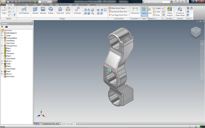
The Fork Crown part (from the suspension fork dataset in the Samples folder). As you can see, it has a multi-item feature and history tree detailing each operation used to build the part.
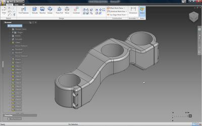
Importing the same component into Inventor Fusion give you a dumb solid which you can edit. Using the Recognize Features command will interogate the part and find features that Inventor Fusion can replicate, such as fillets, holes and patterns.
Making edits
When it comes to making changes to parts, I’ve found it’s best to dive in and work with the data directly, using a combination of the Press/Pull and Move command to edit the geometry, shift it and work with it. When working with direct modelling tools such as this, it is important that you realise that all these systems (without exception) have quite specific limitations in terms of topology. While you can move, push and pull faces seemingly at will, the model must remain watertight and closed and the geometry/topology must solve. When you see faces disappearing, this is usually in the area of fillets and such, where the underlying modelling engine can handle the removal of those faces and patch the surfaces back it. If you try to make too drastic changes to complex geometry, perhaps to move features across faces and boundaries (particularly when those faces are non-planar), you’ll run into trouble and the operation will fail. The good news is that, as with many similar systems, Fusion gives you good feedback about what the system can do and will clearly flag up problems.
Working with Assemblies
The Constrain panel gives you access to assembly both parts and multiple bodies within a single part file.
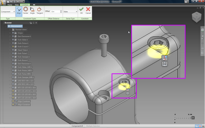
Alongside the part modelling and editing tools, Fusion also allows you to create assemblies using some basic mating tools. As the system is multi-body in a single part capable, you can work with both explicit seperate parts or use the same alignment and mating tools to build up an assembly using mulitiple bodies. Found when clicking the Constrain icon in the Home panel, the basic commands are Align, Center, Angle and Tangent, all with offsets where appropriate. One thing to note is the order in which you select your mating geometry is key. As Fusion doesn’t have a fix or Anchor command to lock the first part down, you need to remember that your first selection is automatically locked and the second selection moves to it.
The Anchor glyph denotes that the first selection is locked and your next selection will move to it.
Annotating your data
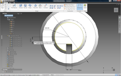
Now, while the name of the Fusion game is direct editing of geometry, you do have a range of dimensioning tools, either for creating precise geometry or for annotating your model. In the former, the system allows you to create dimensions to position geometry exactly using the usual methods – but the system isn’t really geared up for that yet. When it comes to annotation of a model, the system follows the new 3D annotation methods that are being introduced across the industry.
Dimensions are added directly to the model (rather that to a drawing) and you have the ability to add dimensions to specific work-planes. These can be specified directly or dynamically. As there could be a complex set of annotations, you can switch between existing annotation planes (using the tab key), which lets you keep order in your dimensioning schemes. You can also toggle between ANSI and ISO methods of dimensioning in this release.
Next up we’re going to have a little chat with Kevin Schneider at Autodesk about the launch of Inventor Fusion, what Autodesk’s plans are and where this is all headed. Look out for more later in the week.


