
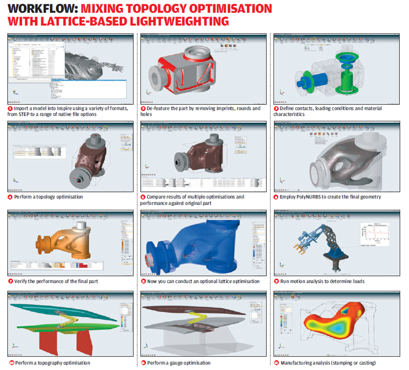
solidThinking Inspire 2018 – Topology optimisation is all the rage these days, but Altair’s solidThinking Inspire has long been ahead of the game. With increased interest in the field, we explore how the latest release might keep it in pole position
Never before has there been such interest in the subject of topology optimisation. Driven by revitalised additive manufacturing techniques, the decades-old subject has been getting fresh attention, both from new market entrants with new tools and established CAD vendors. Either way, both camps seem to be falling over themselves to introduce these tools in their latest releases.

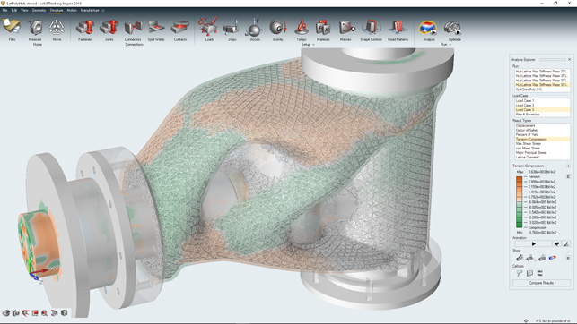
solidThinking Inspire now allows you to explore the potential for using lattices as part of your optimisation processes
But one vendor in particular has been banging this particular drum for a good decade or more – and that’s solidThinking, along with parent company Altair. But while the company’s high-end tools like OptiStruct have long been used in aerospace, for example, it wasn’t until the release of its Inspire application that things got really interesting.
Since its 2013 launch, solidThinking Inspire has proved itself to be one of the most readily accessible set of topology optimisation tools that we’ve seen and its headstart on the competition means it is now much further down the road than many.
Not only does solidThinking Inspire contain the basics in terms of modelling tools for domain design (as well as healthy import options), but also, in recent releases, we’ve seen the introduction of manufacturing constraints (for draft angle and such), motion simulation (alongside the standard linear static analyses) and PolyNurbs, which allow you to very quickly use a sub-D-like approach to interactively model smooth forms over your optimised mesh forms.
solidThinking Inspire – load case definition
The first update we’ll cover is how you define your load cases. Those that already use topology optimisation will know that basing your processes on a single load case isn’t the wisest of moves. Most products have multiple load cases that need to be accounted for, rather than a single, idealised case.
While Inspire has for some time allowed you to define multiple load cases that feed into the optimisation process, these can be time consuming to set up.
From the 2018 release onwards, you’ll be able to import load cases and load table values via spreadsheet format (as CSV or XLS files), whether you want to quickly generate those loads, reuse the data from existing FEA studies in other systems or from physical tests.
This is done by setting up your loads and constraints and using the ‘loads’ dialogue to import a spreadsheet that populates this data for you automatically from your given data source.
Also on the loading conditions front, there has also been work to make motion simulations more useful in the optimisation process and to allow you to include spot welding contacts between appropriate forms.
solidThinking Inspire – overhang control
Before we get onto the big news for this release, it’s also worth noting an addition to the existing manufacturing controls in Inspire. Previously, it was possible to add controls for draft angle control for parts you intended to cast and much more, meaning that the optimisation process could target a much wider spread of manufacturing processes than pure additive manufacturing.
This release does the same, but with a focus on additive. As most readers will know, additive manufacturing systems have specific restrictions in what can be built without support structures, referred to as ‘overhang angle’, especially when you’re talking about metals.
If you can optimise a part’s form to avoid exceeding this angle in the specified direction, then you’re looking at a part that will be quicker and cheaper to build and will require less post-processing work.
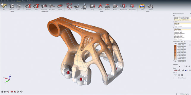
Using topology optimisation and PolyNURBS to model up a structural form, then adding lattice where appropriate
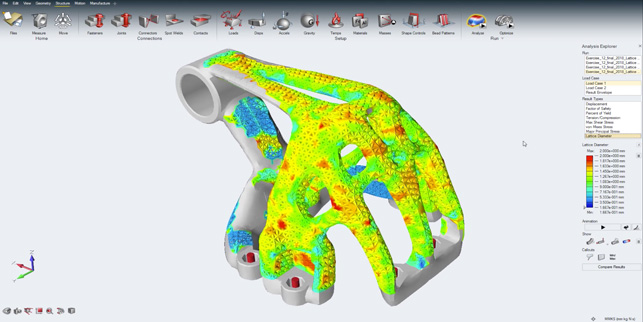
A bulk latticing on a similar part – note how the overhang manufacturing control is also in place in this part
solidThinking Inspire – lattices & optimisation
The big-ticket addition for this release of solidthinking Inspire, however, is the introduction of lattice forms as part of the optimisation workflow. While the software has always focused on the removal of material to achieve an optimum solid form, the introduction of latticing takes this a step further.
This enables you not only to reduce mass using the brute-force approach of topology optimisation, but also to further optimise your forms using the structural efficiency of lattices where appropriate.
The use of lattices fits into the Inspire workflow nicely and if you’ve already tried the system, you’re not looking at a huge change in process. There are two modes in which you can use latticing: either as a bulk job, where you’re looking to convert the bulk of the mass of your part to a lattice form; or to replace solid material with something more lightweight.
The bulk lattice workflow is pretty much as you would expect; you set up your optimisation study with starting domain/design spaces, keep-out zones and other factors in place, along with the load cases you want to use.
Then you define the latticing options. This is done by switching to the lattice mode, then defining your options. Whether you’re working to maximise stiffness or reduce mass, you will get lattice-specific options such as spar or beam length, min/max beam width and percentage fill.
The system will then start to work out how to best place your lattice, where it needs thickness and/or where it can be backed off.
If you’re looking to swap out your mix and match your solid geometry with lattice work, you’re looking at a very similar workflow, but using the traditional optimisation tools to find areas where solid geometry/parts can be swapped out for lattice, then working to define those areas as design spaces, then calculating the lattice for those spots.
As ever, you’ve got all of the validation tools at your disposal for your results.
At any point, you can dive back in, make adjustments, test them virtually and finalise your form.
Fitting PolyNURBS
SolidThinking introduced PolyNURBS in the 2016 release and these took the system from providing the user with a pretty rough mesh-based inspiration for design rework (hence the name), to being able to generate smooth and finalised forms.
PolyNURBS focuses on a highly interactive method that allows you to select two sections through your mesh model and it’ll automatically create a subdivision surface form between them.
You then add further sections to quick add geometry around your mesh. There are tools to quickly snap together joints and you can dive in and adapt each section of the cage built around the form at any point.
This doesn’t change hugely in this release. All of the tools are still there. What it does do is address an issue where the PolyNURBS forms don’t fit too closely to your mesh (perhaps where there’s a sharp change in size of mesh, for example).
The new ‘fit’ command will do its best to adapt your PolyNURBS skin to your mesh, so you’re ensuring that your optimisation work is carried through the remodelling process.
In terms of workflow, this is a nice addition; it means you can quickly lay out a rough patch of surfaces across your part, then use the ‘fit’ operation to snap that set of surfaces more closely to your optimised mesh geometry.
To enlarge image click here
In conclusion
solidThinking Inspire is an incredible bit of kit, which has been leading the topology optimisation field for some time. Only now are we seeing some of the CAD vendors start to catch up, with the introduction of their own surface skinning tools.
Inspire, however, remains one step ahead, by giving users the chance to re-engineer and tweak results where needed – something that other systems simply don’t do.
On top of that, solidThinking has now brought latticing into the equation, which has a huge range of benefits, especially when it comes to the design of specialised components (such as filters or medical implants) that need to be lightweight but structurally effective.
The implementation of latticing in this release is impressive. It allows you to use a combination of topology optimisation and latticing technology where most appropriate. It doesn’t have the fuller set of lattice control forms you’d get in other systems, admittedly. For now, you’re looking at a single lattice cell form to optimise placement and width of lattice beams only.
But when it comes to using these types of forms, it’s still early days. Many companies are still working out for themselves how to make them pay, considering the changes required to cost calculations and production processes. What we need to be able to do right now is to experiment before heading into production.
While solidthinking Inspire looks like an industrial design tool, it’s backed up with world-leading simulation technology. That means that you’re optimising your products on the most informed inputs, from multiple load cases from previous simulations or physical tests to simulations conducted in the system.
| Product | Inspire |
|---|---|
| Company name | solidThinking |
| Price | on application |


