
While not one of the major name players in the CAD world, Delcam has been around since design and manufacturing started to move to 3D. From its inception in the 70s, the company was the first to machine parts from 3D geometry, was adopted by Volkswagen and other major automotive when most CAD/CAM companies weren’t even in existence, and now has one of the broadest ranges of CAD/CAM software in the industry.
Delcam’s product offering covers everything from reverse engineering, design, engineering, manufacturing and NC programming to inspection and metrology. While its company name is founded on its mastery of complex machining, at the heart of its product portfolio is PowerShape. Over the past ten years PowerShape has evolved from a tool designed to overcome common problems associated with handling complex surface-based mould design, into an all encompassing system for conceptualisation, design exploration, engineering design and into the world of production geometry creation.

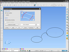
Automatic surfacing with PowerShape: Start off with a simple geometry set – two circles and a connecting arc
One thing that’s been ever present in PowerShape is its ability to wrangle geometry from a wide variety of sources in order to create production-worthy components. When software is used within the mould and die sector, it gives the code a slightly different perspective, as fixing problems in pre-existing geometry is typically much more complex than creating it from scratch. Because of this, PowerShape has been built on the foundation of a hybrid modelling approach, where both surfaces and solids can co-exist within the same model and use the same creation and editing techniques. Hybrid modellers typically have a much greater depth of functionality with regards to diving in and creating surface geometry in the exact form required.
While PowerShape has this capability at its core, Delcam has built on this over the past four or five years in two key areas. Firstly, it has added history- and feature-based modelling. This is in stark contrast to many mainstream vendors, who have started with solid modelling and then begun to introduce more surface modelling workflows – Delcam has been doing it in reverse.
PowerShape has evolved into an all encompassing system for conceptualisation, design exploration, engineering design and production geometry creation
Secondly, the company has introduced the ability to handle a third modelling technology in the shape of polygon mesh data. This could be from reverse engineering or more artistically-led geometry creation tools, such as its ArtCAM software. To describe this combination of three types of geometry – solids, surfaces and mesh data – Delcam has even invented the term “Tribrid Modelling.”
The end result is a system that can create part geometry from the simplest of prismatic features, from more complex surface-type geometry or, uniquely, integrating both of these with mesh-based geometry. What’s interesting is that not only has the company introduced these new technologies to enhance existing ones, the whole system has been through a complete rework to make the working environment more engaging, modern and easier to understand.
Introduction of Parasolid
The 2010 release sees a couple of fundamental changes in PowerShape. The biggest news is that Delcam has adopted the Parasolid kernel. This gives the system, and inherently the user, several advantages. Firstly, it gets what is probably the most robust modelling kernel on the market. Practically speaking this means quicker geometry creation and a more reliable set of features, particularly when creating fillets and blends.

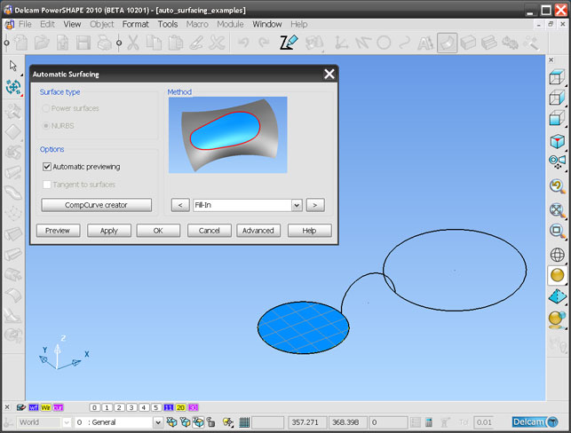
Automatic surfacing with PowerShape: Select the smaller circle and it produces a planar fill surface
Alongside the functional modelling benefits, Parasolid also brings greater interoperability with supply chain data. Parasolid is at the heart of the majority of CAD software currently on the market so there’s no translation of data when working with the likes of SolidWorks, Solid Edge, and NX. Instead if data is read into PowerShape that has a Parasolid base, then the system simply rips out the Parasolid data and loads it into the session. And of course, PowerShape can pass out native Parasolid geometry to work with these systems too.
Solid Doctor
Working with less than perfect data is often a problem, particularly for those working with complex sculpted shapes. To address this PowerShape 2010 includes a new group of commands called ‘Solid Doctor’. This collects together a number of common fixes for geometry problems, whether that’s adjusting tolerances, removing small or twisted faces, plugging holes and so forth.
Solid Doctor is presented in a small, simple dialog, in which the part is inspected, the errors grouped and fixes suggested. The user works through the most common fixes, the system rechecks the part and moves onwards until there is a watertight model. If serious issues are found, the user can dive in, use PowerShape’s geometry editing tools to fix it manually, and then rerun the checks to validate the work.
Smart Surfacer
Surfacing is a complex business. From first principles, when trying to create sculpted, intricate forms, it’s an inherently more involved workflow than when working with prismatic features. The geometry is more complex, so the creation of it is going to be more complex, right? Traditionally, yes. Surfacing requires that a network of curves is built first, with the precise form of those controlled by not only the shape users want to create, but also how they want to create it.
There are many types of surfaces. Planar surfaces are flat and the simplest. Then there are four sided surfaces, n-sided, bi-rail surfaces, extrudes, lofted surfaces, swept surfaces, blends, flanges, and fillets. Filleting in itself is a very complex choice depending on the form requirements. When working to corners, the user is trying to merge three or more surfaces that converge on a single point and at this point may want to use different fillets, with different set-back values.
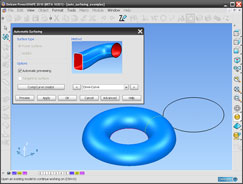
Automatic surfacing with PowerShape: Add in the connecting arc to the selection and it’ll switch to a drive curve, to push the arc around the circle
All in all, it’s an involved and often daunting prospect – particularly for those that have learned their trade using mainstream, solid modelling applications. It’s important that the user has a good idea of the form to be created in advance as this is essential to create curves (often referred to as wires), before actually creating a surface.
PowerShape is one of a select group of products that allows its users to work with intricate geometry, to fix it, and then prepare it for manufacture. This capability is essential to its users as they often need to transform problem third party data into flawless data in order to turn a design into a manufacturable product – something that requires highly efficient tools.
Perhaps the perfect example of this is how PowerShape handles surface creation. Users are often faced with multiple decisions about what curves and types of surfaces they want to create, before they’ve even started to think about creating geometry. Smart Surfacing is designed to take many of these decisions out of their hands – or at least to give a helping hand along the way.
The user starts of by creating a curve network and then invokes the Smart Surfacer command. This presents a simple dialog box. With this active, the next stage is to select the geometry, either from curves or from existing surface edges. The system inspects the selections, looks at the types of surfaces it can create, then presents its choices for the best type of surface that could be created based on that selection.
As more geometry is added to the selection, it re-evaluates the choice and switches the surface type and displays a preview. Users have full control over the form it creates, but the chances are that the system will create the required geometry in the first instance. For those working with less than ideal curve or edge geometry, the dialog also includes a composite curve creation tool, which allows users to merge edges and curves to get close to that four-sided surface ideal.
Conclusion
Some of the things I’ve discussed here aren’t new to PowerShape, but rather extensions and enhancements to tools that have been in the system for some time. In doing this I’ve tried to get across the point that PowerShape is an incredibly rich application for the creation, modification and repair of complex geometry. It always has been and always will be.

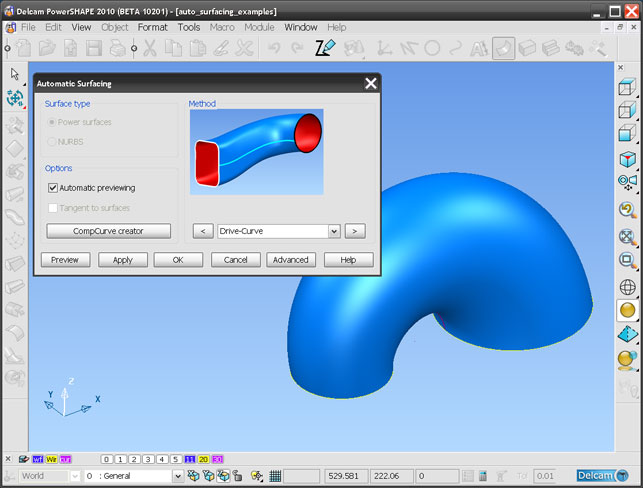
Automatic surfacing with PowerShape: Adding in the large circle maintains a Drive Curve, but runs it between the two circles, using the arc as the Drive Curve
The simple fact that users now have the ability to model using surface modelling and solid modelling operations and integrate that alongside triangle-based data only goes to increase that power.
The introduction of the Parasolid modelling kernel should also increase the power of the system. After all, the PLM Components team at Siemens has spent years developing a robust and industry-proven modelling engine and it makes huge sense for Delcam to piggyback on that and integrate it with its existing tools. This means more robust feature creation, faster modelling and much enhanced data translation.
For those with an interest in creating and working with complex forms, then PowerShape is definitely worth further investigation. The good news is that a version of the software is available for anyone to use in the form of PowerSHAPE-e. The only limits of the system are that it can’t export data, uses an encrypted file format that can’t be read by commercial PowerShape licenses and has no rendering. Download it, try it out and see what your CAD system should be able to do. It’s as simple as that.
| Product | PowerShape 2010 |
|---|---|
| Company name | Delcam |
| Price | From £5,000 |


