Following on from his previous simulation workshops, Laurence Marks is back and this time he’s looking at the process of topology optimisation
In the intervening two and a half years since my last series of simulation articles, topology optimisation has seen its profile grow and grow.
This has been driven by the inexorable rise of practical and useful 3D printing, which allows us to manufacture all manner of creative forms. But optimisation isn’t a magic ‘better product’ process that just spills out lighter, stronger and more durable products; if you think there are any free lunches in this game you’ve not been doing it long enough.
Generally, in the early days of Finite Element Analysis (FEA), you would model what had worked previously, or somebody’s best guess at what would work, and gave it a yes or no. Then you’d possibly look at some small mods to improve it. There just wasn’t time to do anything else. Designs were still based on experience and the de-facto test program of history; simulation had a sort of goalkeeping function.
As computer power has grown and software packages have become ever easier to use, simulation is now more central to the design decisions that engineers and designers make everyday. But that means decisions made around simulation are ever more critical.
In this article there isn’t time to cover all the bases, which if we started to list them would look something like: does the model represent the actual loads and boundary conditions well enough? How does the production process influence what we say about the material, its response to loads and what we allow it to see? What subset of the multi-physics world are we going to base the optimisation parameters on? What optimisation parameters are we going to use and what should we set them to? What are we going to do with the geometry that comes out of the optimisation system?
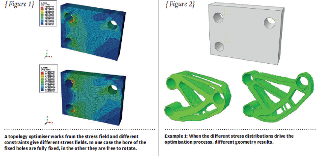
So the first aspect we’ll look at is as basic as it gets. We all know that the results from an FEA study are critically dependent on the constraints we define and how closely they represent reality. In the example model in Figure 1 I’ve defined two fixed regions.
In one we’ve used the wildly over utilised fully fixed constraint whilst the other has a ‘more realistic’ radial constraint representing the fact that the material can rotate around a fixed cylinder. The real behaviour in a bolted joint is generally somewhere between the two.
The simulation results are markedly different between the two cases and therefore the structure which automatically emerges from a topology optimisation is very different. If we’ve optimised to the wrong problem definition what comes out may be a long way from optimal for the right one. It might not work at all.
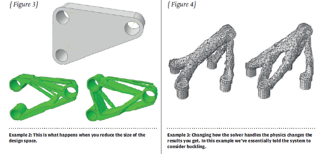
The second example in Figure 2 looks at the design space. You may have a really restricted design envelope (topology optimisers seem to struggle when this gets very restricted) but if you can expand on this, even by a small degree, the scope of the solution is increased, allowing it to create lighter more efficient structures. This is one area where the initial intuition of the designer is contrary to what the approach really needs. Restricting the design envelope has a big impact on what you get.
If we get the constraints and the design space right there is then the question of physics.
In my last series of articles we looked at how complex the world of simulation can get. Most topology optimisers can only handle a subset of the many sorts of solution physics, but the one used in this article can handle the effects of non-linear geometry (as well as a number of other complexities).
It deals with how loads applied in one direction can’t do –1 times the other load direction. In the example in Figure 3 we’ve switched one setting in the solver (include non-linear geometry or not) and the results are quite different.
These are just three simple illustrations of the bigger picture I mentioned at the start of the article. I haven’t even looked at getting the optimised shape into a manageable form, and if you do, you then have to look at whether that optimised design can actually be made. The question then is: what will the process do to the material and internal stress state?
As I said, no free lunches but lots of scope to create components that are a step up from the current state of the art.
Laurence Marks is MD of Strategic Simulation and Analysis Ltd, a company supplying the Simulia range of simulation software, training, implementation as well as consultancy services to a wide range of industries


