Kicking off with changes and enhancements to the user interface, the first thing to notice is that the whole system is 64-bit compatible.
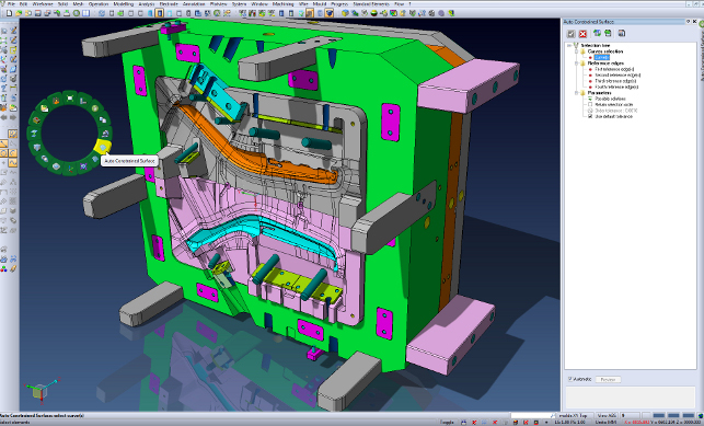
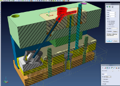
A new radial menu gives the user a selection of context sensitive commands
While for those working on smaller parts and tasks, this shouldn’t have too much of an effect, for those working with large geometry data sets, plastic flow calculations or complex machining toolpaths, this will be a huge benefit.
Elsewhere, there are updates that should help every user, particularly the ability to dynamically preview a file before opening it. Rather than using a preview built into the design software, this is integrated into Windows Explorer and available in every application.
Having selected a file, the user is presented with a preview rather than just a static thumbnail image. This can be panned, rotated, zoomed and even includes rudimentary sectioning tools.
It also shows the key metadata for the file including name, description, revision etc. This is enabled by some clever trickery and together with the updates from the last release, it allows just the graphics portion of a data file to be loaded.
This release also sees continuing work done on how the user interacts with VISI’s various tools and how models appear.
As well as all the usual bells and whistles for graphics display such as shadows, reflections and glow lines for wireframe selection, it also brings more shortcuts.
The right mouse button now brings up a radial menu that, by default, provides a selection of context-sensitive commands.
This can be configured to the user’s specific requirements with four, eight or sixteen commands in any one menu. It can then be further expanded by using the Alt keyboard modifier.
On the more technical side, there’s been work done to how VISI’s features are defined, making them more flexible and removing the requirement for a very explicit workflow. A good example is the creation of elements such as body cuts and wireframe sections.
Previously, users would have needed to fully define where and how such features were created, whereas now the feature can just be added into the model approximately and dragged into position with the specifics locked down later.
Mating & exploded views
VISI’s background is predominately in the mould and die market, which has meant that introducing more sophisticated assembly constraint and motion controls hasn’t been a priority.
However, having recognised that its user community is widening, this has changed for VISI 20.
The new set of tools has the usual array of constraints, including concentricity, coincidence and distance. But what’s different now is that the user doesn’t have to work through each part individually, as is the case with most other systems.
Instead, a group of components can be selected and then assembled to another set. When you consider that VISI often works with a combination of native and imported geometry, this makes a lot of sense.
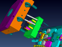
It’s also possible to move assemblies, explore their movement and detect collisions, even stopping where they’re found. This is ideal for those working with more complex die designs or injection mould tools where movement is required within a limited space and interference between components has to be eliminated.
These tools then link into exploded assembly tools. These are step based so each component is moved to the appropriate position/rotation angle, and it shows how a mould stack opens up or how a progressive die moves through the process.
Of course, these can also be animated and exported as movie files to share with clients and management.
Modelling
With such a mature product, much of the work in VISI 20 has been focussed on operator workflow and command efficiency.
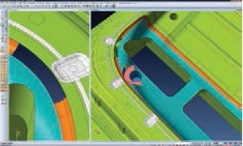
The first key update worth mentioning is that it’s now possible to sketch curves directly onto a face, or set of faces. In previous releases, this required creating a 2D sketch then projecting it onto the surface but from now onwards, the user can do it directly on the surfaces.
This will be ideal for manipulating split lines when working with complex geometry. When combined with the previously discussed workflow flexibility, it’ll be a much easier process than before.
Sticking with wireframe geometry, VISI 20 also delivers a redesigned wrapping tool, and new splitting options that automatically colour the individual segments for easy identification.
The other major update to modelling capability involves the Automatic Constrained Surface tools introduced a couple of years ago. These centre on the automation of surface creation.
Sketch out the driving wireframe curves (or select the edges from existing surfaces) and have the system decide which type of surface best fits the geometrical conditions.
Instead of just providing the final result, it now allows the user to switch the actual type of surface used from tangent patch, N sided patch, advanced lofting and two directional lofting.
Working with bad geometry
While the geometry creation tools are key, the ability to work with customer geometry, regardless of quality, is absolutely fundamental.
Many will be familiar with some 3D systems’ insistence on breaking up curved edges into smaller facetted edges. The problem with these type of forms is that either filling-in surfaces for tooling, building out parting surfaces or just fixing the data is often a nightmare.
VISI has always had tools to manage this scenario, but this was often the task of an expert user. But new tools in VISI allow the user to work with these types of edges and automatically concatenate into a single curve, removing redundant vertices and node points, and splitting the geometry into sensible curve combinations based on angular deviation.
Ultimately, the cleaner wireframe geometry, combined with the constrained surface enhancements, results in a much better surface.
Feature-creation & editing
While VISI undoubtedly mastered the manipulation of dumb geometry quite some time ago, the last few releases have seen the team introduce more feature-based edits.
This has predominately been done to assist with either making intelligent changes to geometry or to defining manufacturing parameters up front.
The changes for this release are both at the core of the tools, but also the way in which users work with feature data.
In terms of fundamental updates, the feature technology has been rewritten and can now be customised by users with knowledge of the Python scripting language.
As ever, the Feature Manager is the place where all the typical features show up, such as holes, pockets and such, but this can now be expanded to manage whatever geometrical forms the user or organisation requires.
Alongside this, there’s also been work done to make the editing of multiple features much easier. The system now allows the user to validate all the features within a part, filter them to narrow down the selection, then make global edits to all of them in one step.
This can be done either by dialling in new values or selecting reference geometry to match specific requirements.
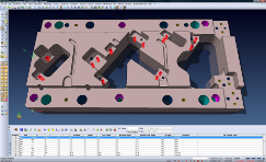
These tools can also be used in the documentation stage. For example, if a boring chart is required, the user can start with either the 3D or 2D geometry, define a datum and have the system strip out the hole data such as hole type, drilling cycles required, position etc.
This is one of the advantages of having in-house feature recognition tools driven by CAM needs. The system can very quickly process multiple set-ups and return a tabulated listing of all the drilling required in a set of parts.
This information is typically plotted along with the tooling GA or exported as a CSV or TXT file for the shop floor.
Conclusion
When you take the wider view of the last few releases of VISI, it’s pretty clear that the customer base is changing.
While the company’s stronghold has always been the mould and die market, both for design and machining, this looks to be expanding.
There are a few changes in this release that indicate moves to support multi-user use of the system, which I suspect will show greater benefits in the next year or so.
Other updates, such as the ad-hoc network based computation of many tasks that we’ll discuss soon, also show that the company is gearing up to support multiple users and making their use of the system more efficient.
So, let’s wrap things up there, then dig into the updates to the CAM tools, the flow simulation tools and die design later.
| Product | VISI 20 |
|---|---|
| Company name | Vero Software |
| Price | from £2,000 |


