

SolidWorks one of the industry’s leading 3D CAD tools, needs little introduction, so I’m going to kick things off with a look at the enhancements that have been made to the core tools and user interface.
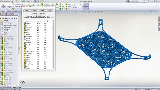
Feature Freeze allows the locking of specific features (typically early in the feature history) so they are not included in recalculation processes
For long time users of SolidWorks, the chances are you’re running multiple monitors. While the 2011 release gave you the ability to span the entire user interface across multiple displays — though to be
frank, without that much control — for 2012, the controls are much more sophisticated.
Small icons at the top of each window can be used to automatically arrange ‘open’ files across multiple displays, switch windows and such – making the whole thing much less of a faff.
Other small, but equally useful, updates include the ability to ‘Control+A’ select everything in both the feature and part PropertyManagers, as well as sketch elements. Mouse gestures have been updated to include ‘accept’ and ‘cancel’ to save you rooting around for the right click or UI-based options. Also on the gestures front, you can now invoke macros directly.
While there’s a tonne of updates all across the board for this release, I wanted to pick out a few that struck a chord with me and cover them in a bit more detail, so here goes.
Data import workflow: This is something many users come up against, particularly when working with highly complex and multi-part assembly data in third-party formats.
Traditionally SolidWorks parses the files, works through the assembly structure, then saves out both the assembly references and the individual part files to disk as it steps through the process.
Often a lengthy process, it can give you a bit of a headache, particularly with large assemblies. To save time, the 2012 release can now be forced to hold the parts in memory, then only when you want, save the data out to disk.
Another update to data import workflow (although it also works across normal File/Open operations) is the way SolidWorks deals with missing components. It now retains a list of referenced folders you’ve
previously looked in for missing components and checks them before asking you to select a new folder. A nice time saver.
Command search: One big update that’s going to be really useful is the change to command search. Typing a command into the small box now brings up a list from which you can select the appropriate action.
If you’re looking for the location of the command, then SolidWorks will also point you in the right direction – you can even drag it out and add it to a toolbar. We all have workflows and commands we use
everyday, but this makes the whole system much more accessible.
Feature freeze: This is going to be a big one,particularly for those working with complex parts with large feature counts or very complex parametric relationships.
There are many instances when you might not want to recalculate an entire part’s feature history. For example, when adding detail to a complex geometric form, it may be useful to freeze the earliest features that define the form of the part, so only the engineering features update as you ‘play’ with their position and work on their form separately. Feature freeze allows you to define a point from which the recalculation happens.
Ambient occlusion: The final core update is to do with display graphics. There is now a switch to maintain ambient occlusion for realistic shading, which in previous releases would have switched off when you zoom or rotate your model.
While this might sound a small thing, it will certainly be welcomed by those who use SolidWorks for design review and presentation. It’ll make things look slicker and present models in a much more realistic manner, but there will likely be a performance hit in terms of graphics resources.
Multi-body modelling
Multi-body part modelling is something I’ve used in various systems since the year dot. The ability to hold a complete representation in a single part file, even if it does contain parts that would typically be stored as separate files, makes huge sense — particularly when you have complex geometric and functionality relationships between those parts.
SolidWorks has supported multi-body modelling tools since 2003 and these have now been worked on and enhanced for the 2012 release.
One area in which the tools are used most is in weldments and frame design — where a single ‘part’ comprises individual parts that are used in its fabrication. When documenting those parts from a single data source, however, it wasn’t as easy as it could be, particularly when creating exploded views.
This has been solved for the 2012 release and exploded views can be created from multi-body parts without a problem.
Equations
One of the fundamental components of any parametric modelling system is, of course, parameters. It’s these relationships, the interlinks between various inputs and controlling dimensions, that can transform a dumb 3D model into something breathtakingly intelligent.
However, in SolidWorks, creating anything other than basic relationships between geometric elements has often been quite complex. Prior to 2012 it required the use of a separate dialog, alongside a couple of different entry points and methods, which varied according to whether you’re working on single parts or across sub-assemblies, etc.
For 2012, this has been rationalised into a single dialog across all modes and functions. It allows you to flick between equation view, dimensions and parameters.
Elsewhere, the Equation Solve tool now runs in real time as you’re adding intelligence to your model, either correcting your actions or making suggestions. Along with the syntax highlighting, this will help save you those few minutes of head scratching when you’ve got the slightly wrong reference or symbol in place.
When you start to add references, the system also will also drop down a list of all the inputs to make creation easier.
Large design review mode
Now, this is something that many users have been crying out for over the last few years. With hardware advances, and the advent of 64-bit computing, workstations can now handle huge datasets and users are certainly making use of this increased capacity.
Consider the state of the art within SolidWorks. It’s now possible to hold multiple geometric representations, piping, harnessing, electrical and electronic data, simulation studies and much, much more all within a single assembly.
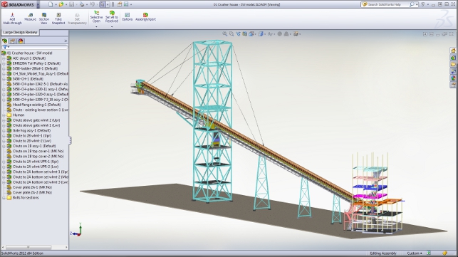
The downside is that when handling all of this data it can dramatically affect the performance of your workstation. To help combat this, 2012 introduces Large Design Review mode. This combines previous work done with lightweight and resolved/unresolved geometry loading to make the handling of large datasets more efficient.
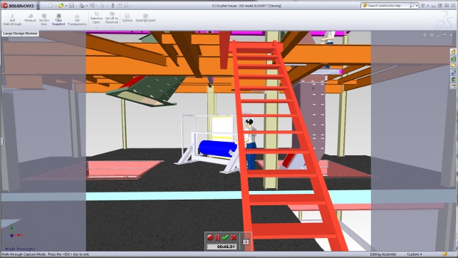
In essence, SolidWorks only loads the product structure (the assembly, sub-assemblies and parts list) and the graphics. Once loaded (typically in a fraction of the time it usually takes), the model can be manipulated in terms of pan, zoom and rotate, but walkthroughs can also be conducted, geometry measured, and sections created.
There’s also a snapshot function that allows the view state to be stored and if portions of the geometry are then required for editing or further work, they can be loaded into memory and worked on. Once finished, the full description is then unloaded from memory and the graphics only display switched back on.
Motion optimisation
For those that have been digging into SolidWorks’ expanding set of simulation tools, the introduction of ‘motion optimisation’ is going to be very interesting indeed.
Geometry optimisation of structural performance was added to SolidWorks Simulation a while ago, but the new ‘motion optimisation’ tools allow you to work with parametric assemblies to find the best solution to a set of given requirements and conditions. Key to this process is the use of sensors, which set goals for motion optimisation (they can also be used in structural optimisation).
By no means a new concept in 3D design technology, sensors allow the definition of specific measurements within a study, whether that’s in terms of geometric limits or performance requirements. They define how the required outputs are measured, either in terms of a straight output value (useful for geometric dimension requirements for fit and function) or, the more complex process of using expressions and equations.
In terms of motion simulation, sensors can be applied to motors, springs, dampers, contact conditions and almost any other properties resultant from a study. Studies can be either run as an optimisation process with ranges for variation set to find the optimal conditions or, if a better understanding of the various constituent parts is required (such as using standard components), a design of experiments can be performed.
Drawings
As you’d expect from any SolidWorks release, there have been a few updates to the drawing and draughting capabilities.
A big one is that it’s now possible to open up a part or a sub-assembly from a drawing, rather than having to open the master assembly first.
Other updates include a tracking tool that will flag up where dimensions and other notes have been changed (in terms of the geometry they reference) with an additional reference to show what the previous dimension was. This is all done using colour changes.
Another one that’s been a long time coming is the ability to create a Bill of Material (BOM) on a separate sheet to the originating view.
Centre marks can be added into views after they’ve been created, and you have the ability to reset and reuse detail, section or auxiliary views numbering/lettering schemes, so your drawings are all in order.
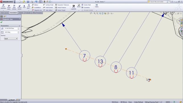
The final update I’ll cover is a good one, particularly for those that also use the 3Dvia Composer application — the Magnetic Line from compose has made an appearance in SolidWorks’ draughting tools and it’s super useful for arranging balloons around your geometry.
You grab your balloons/call-outs, tie them to the line and drag them into position by dragging and dropping the ends of the line. The system handles the spacing and alignment for you — perfect for getting those presentation view just how you want them.
Conclusion
It’s been interesting seeing the reaction to SolidWorks 2012 across all the various blogs and websites. Many seems to think that there’s not a great deal in the software, but when you dig into those opinions, it’s often the case that the author is concentrating on pure geometry modelling tools.
In that regard, I agree — in terms of updates and enhancements to the tools used for modelling the geometry of a component, SolidWorks 2012 is not one of the stronger releases we’ve seen over the last few years.
But then step back and look at it from a wider point of view. The updates made to simulation alone are pretty huge. Our data shows that SolidWorks users are amongst the leaders in terms of adopting simulation technology and the tools in this release, such as the motion-based optimisation tools and sensors, are likely to garner a lot of interest.
The new SolidWorks Costing module is another massive update that finally starts to bring cost and price into the digital modelling realm, closing a hole that’s been gaping for some time across the industry.
Elsewhere, other updates to the sustainability tools, large assembly handing capabilities, through to the drawing functions, all add to an already all-encompassing system. The transition of features from 3DVia Composer is also a trend that’s encouraging to see — one of cross-pollination between Dassault Systèmes’ family of products.
Many are trying to second guess what Dassault Systèmes and SolidWorks are up to as they prepare SolidWorks V6 for market — but to my mind, it seems that there’s still plenty of work to be done on
the current generation SolidWorks and it’s clear that the work is still being put into the core product.
One thing’s for sure, with the huge SolidWorks user community, depth of product and third party applications, I would predict it will span the best part of the next decade.
SolidWorks Costing: price up your digital model
When you talk about product in development there are essentially three factors that influence its ‘success’: form, function and cost.
Modern 3D design systems are perfectly capable of providing accurate information about the form and function (the latter through the use of simulation technologies). However, the last of that holy trinity, cost, is often disconnected when most critical — during the development process, where costs are built directly into a product.
Material resources, manufacturing and assembly process, and packaging are all influenced by the form and function. While there are technologies out there that sit alongside the workhorse design tools, there’s been no great shift to see ‘costing’ brought into the heart of design systems — until now, that is.
With SolidWorks 2012, Dassault Systèmes has introduced SolidWorks Costing. The goal is to provide a set of tools that allow a design team to establish the cost of the parts in design as they’re being developed.
The initial release sees the focus placed directly on two types of parts: sheet metal and machined components. In terms of sheet metal components, it’ll work with those specifically defined as such (as opposed to imported data) and uses features such as flanges, punches, bends and formed features to derive a cost against a predefined list.
The machined component capabilities are pretty much limited to 2.5 axis machining jobs with basic pockets, drilling cycles and profiling (whether that’s done with a machine tool, plasma or water cutter).
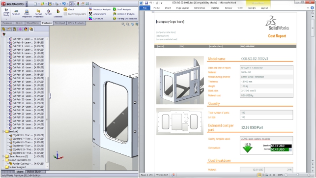
It works like this. The system looks at the component in work and creates a list in the new CostManager tab that splits the part out into the processes and operations required to manufacture it (for sheet metal parts, this is set-up, cut paths, bends, punches etc).
It then compares their size, material and complexity (in terms of operations) against a predefined costing list and gives you a baseline cost for that part. As you’d expect, these costs can vary massively and the template can be edited and adapted to suit your organisation’s prices if you so wish.
What’s interesting is that the system has a baselining facility so that you can lock a base price, then play with the form, the features, the material even and see if costs can be stripped out of it. A cost report can then be generated to assist with documenting the process and to aid decision making.
| Product | SolidWorks 2012 |
|---|---|
| Company name | Dassault Systèmes |
| Price | on application |


