
It seems a little inappropriate that our first foray with FEA in the last issue is now followed up with the same problem but complicated by the addition of contact!
The main reason for this rapid escalation is to underline the potency and efficiency of the 2D axi-symmetric approach. Axisymmetric analysis will give us an excellent appreciation of the problem BEFORE we progress to 3D. All other 2D solutions (plane stress, plane strain, shells and plates and so forth) carry a penalty whereby the real nature of the full 3D problem is lost in some way.
In axi-symmetric analysis there is no such loss of accuracy. As long as the geometry, material properties, loading and constraints repeat for all theta then an axi-symmetric analysis is the most efficient solution method.

If you cast your mind back to last time, we made a simple finite element model of the main structure of the pressure vessel without the addition of threads. Instead of threads we put a shearing/traction pressure on the plain bore where the teeth would be – this traction was calculated to put the vessel in axial force equilibrium.
Our approximation last time was to assume that the threads produce a thrust (“Q”) which was purely axial. This is fair enough for a square/buttress thread but what happens if we have an angled thread?
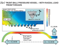
I’m not suggesting you do this yourself but { fig.1} shows a re-run of the vessel-only analysis with actual teeth “cut” into the neck of the vessel.
These teeth are constructed to drawing (measurement or CAD data) noting that the exact axial location of the teeth is not defined because they move as you rotate the vessel (helix angle of the thread).
The threads in our analysis will be represented by annular grooves – a departure from the real 3D problem but not too far that our analysis won’t still be useful.
The traction on the hitherto plain bore is now replaced by normal face pressures on the flanks of each individual tooth. All teeth receive the same pressure value and there is no variation along the length of the flank.
With a 60-degree thread form then the flank pressures generate an outward radial force of 11,191N in ADDITION to the axial thrust of 19,383N. A simple force diagram (see inset on { fig.1}) shows that the radial force, R, is given by the axial thrust multiplied by the tangent of 30-degrees.
The stresses in the neck region should be more realistic now because of the addition of the radial load.
Note that our previous analysis, with the plain neck, could be modified to simulate a 60-degree thread by the addition of a normal pressure (over the parallel neck region) such that the radial thrust force was 11,191N. Try it yourself next time INSTEAD of adding teeth and loading these.
{ fig.2} and { fig.3} show the natural extension to the project in that a threaded valve (and spacer) has been added to the simulation. The valve has been simplified somewhat but has a matching male thread which makes contact with the female thread cut into the neck of the vessel.
Sealing is achieved at the obvious “O”-ring location near the shoulder in the valve body. The simulation carried out here assumes (rather naively) that the internal pressure terminates at the contact point of the two most inboard teeth. We will return to such issues at a later date.
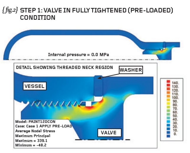
On the understanding that the valve would be subjected to an installation torque (in order to tighten the valve into the main vessel) then the FEA would likely use two loading cases as defined below:-
STEP1 Simulate the tightening process by building in pre-load to the model
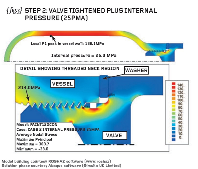
STEP2 Hold pre-load and apply internal pressure to the inside of the vessel
{fig.2} therefore shows the first principal stresses in the vessel assembly at the end of STEP1 and {fig.3} shows the first principal stresses at the end of STEP2.
The stresses in the pressurised vessel STEP2) are seen to be very similar to those stresses predicted in the simple vessel-only analysis {fig.1}.
I would urge you to make the assembly of components in an “exploded” position (well away from each other so that geometry is not shared between them). You must ensure that the individual components are completely separate one from another as sharing nodes will cause the data-check to fail with errors.
I define my contact surfaces (lines in this 2D study) while the components are separated – nowadays the package may identify these contact sites for you automatically and this is termed “general” contact. I make the final assembly of parts with small overlaps defined between mating faces.
The dimensions of each component cannot be corrupted but (here) the axial location of one component relative to the next can be changed such that an overlap can be defined. In this study I have used overlap to define the amount of pre-load captured in the tightening process.
We will do more on pre-loaded assemblies like this but I hope that you can now see the power and relative ease of such an axi-symmetric study. You can afford to throw elements at the problem and still get your answers back relatively quickly – this won’t be the case when we go to full 3D.
R P Johnson BSc MSc NRA MIMechE CEng – technical director, DAMT Limited 
Part nine of an engineering masterclass: ‘Paint-Ball’ Pressure Vessel (2)


