

VGStudio Max – Additive Manufacturing enables the production of infinitely complex parts, but with that complexity challenges arise when it comes to inspection. We look at a system aiming to close that loop with CT data
Best known in the medical field, a computed tomography (CT) scan uses many x-ray measurements to produce detailed images of structures inside the body, including the internal organs, blood vessels and bones. This assists in the diagnosis and monitoring of a variety of conditions. What is less well known is that CT scanning has, for a long time, been used in the industrial world for inspecting not only the exterior but, more importantly, the interior structure of parts too.
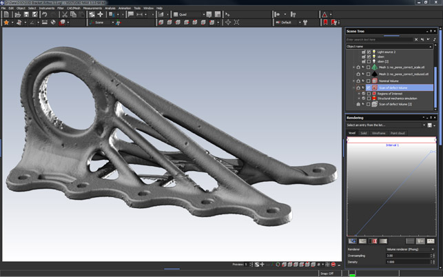
VGStudio Max allows you to read in image-based data from CT scan processes and then reconstruct a holistic representation of your manufactured part — flaws and all
Similarly to how medical professionals can gain an understanding of what is going on inside the human body without the need for surgical invasion, manufacturers can gain an understanding of the internal form of a part without any harm or destruction to the part itself. This accurate internal inspection allows them to find potential voids, cracks or other flaws, rather than pure exterior dimensional inspection.
In addition to the simple inspection of each slice, the tightly controlled nature of CT scanning machines allows a 3D model to be reconstructed using that slice data. This forms the basis for further inspection as well as reverse engineering processes.
While these techniques have been used heavily in the high-end foundry industry (typically with aerospace and automotive leading the way) for many years resulting in well established processes and best practice, there’s huge potential for wider adoption due to other changes in the market.
The groundswell of interest in additive manufacturing, particularly in the metals fields, is causing greater attention to be paid to shape design. From topology optimisation regaining the spotlight to new forms of generative design, there’s more development (and investment) in this area than ever before. Alongside this, the machine and material vendors are pushing ahead with even greater levels of investment and work to bring new machines and materials to market.
But with this increase in interest comes a curious gap in the market and the production workflow. When we’re discussing additive manufacturing (AM), the nature of the build process, particularly with metals, means there is a greater need for a better understanding of the internal structure of a part.
Whether it’s a laser cladding or a powder bed approach, AM typically works with layers, with a boundary and an in-fill, which in reality is hard to achieve. Whether it’s down to errors in each slice, or the build process fails to fuse material together, or there are small issues with powder or feedstock consistency, there are a great deal of variables that can infl uence the structural integrity of a part.
Interestingly, while there’s a lot of development in the up front process to remove these problems through greater and more sophisticated simulation before the part gets built, there’s very little at the other end to ensure that the part that is built is what you actually wanted.
This, as you might have guessed, is where CT scanning can provide an insight into the results based on the final part and it’s where the 20+ year veteran in CT scan post processing, Volume Graphics, has built its reputation.
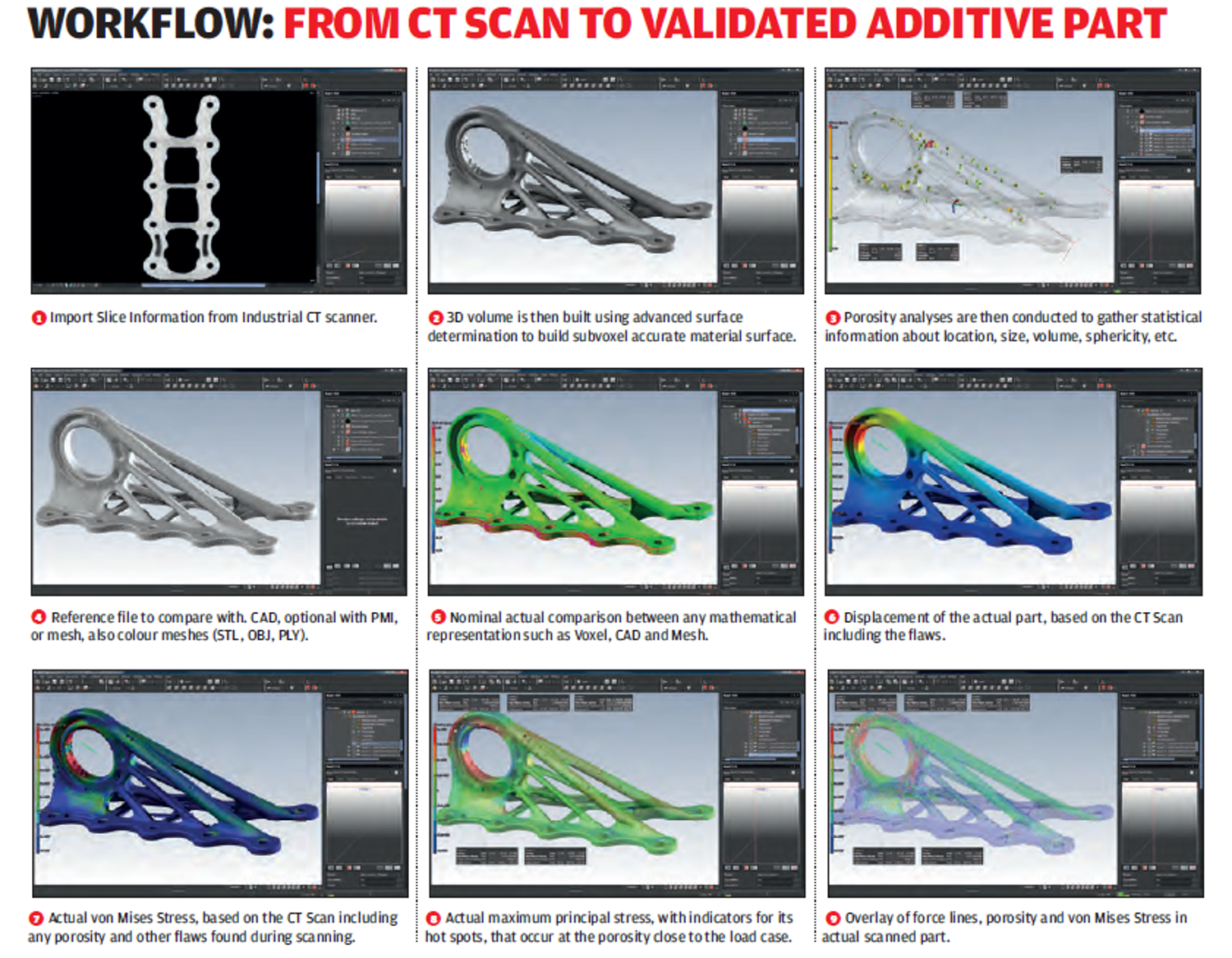
Volume Graphics produces a set of applications that span most of the requirements around the use of CT scanning in the industrial field, from simple reconstruction of 3D geometry from sectional CT data (essentially a set of bitmaps), through flaw detection and into both reverse engineering and metrology. So we’re going to explore how the system works, what you can do with it and how it could benefit an AM focussed workflow.
VGSTudio MAX in use
The first task is to read in the data from your CT scan. CT scans typically output a series of sectional captures through the part in question. These are set as known distances so can be used to construct voxel-based models. As you’ll see from image 1, these models are high fidelity and the software uses some tricks to ensure that the points generated are as accurate as possible.
This is, as you would expect, a pretty computationally expensive process — VGStudio Max uses modern GPU units to accelerate this process and the stress analysis add-on allows you to make use of networked machines as well.
Once you have your mesh model, you’re able to instantly see not only the exterior form of the part but you can start conducting internal inspection of the part’s structure too. VGStudio Max is a pretty modular system, so as you add on each capability, you’re able to do more with that data.
There are a couple of porosity modules, that allow you to locate any pores, holes, inclusions or voids inside your part quickly. Not only in terms of position, but compactness, size and geometry. It’ll also find gaps between these flaws and distance from a reference surface, which is useful for finding flaws near a machined surface in cast or AM parts. If you’re working in the automotive supply chain, there are also more advanced tools for defect analyses in accordance with VDG rules P 202 and P 201 with regards to porosity in automotive castings for ferrous and nonferrous castings respectively.
There are a number of other modules available that then step into more advanced processes. For example, if you’re using filled materials (whether as part of an additive focussed production process or more traditional filled polymers), you can conduct a fibre fill and alignment analysis.
Elsewhere there are tools for those working with foam structures to analyse cell and strut geometries. These, of course, have been built for traditionally manufactured foams, but the same toolset also has implications for those looking to use AM for heat exchange or other filtration applications. Additionally, there are transport phenomena analysis tools that provides permeability, diffusion electrical resistance or thermosconductivity analysis.
Voxels + 3D CAD data
Where things start to get really interesting is when the voxel-based data derived from your CT scan is combined with the nominal CAD data used to generate the part in the first instance.
With this accurate description of both the nominal CAD part and the end manufactured component, a number of comparisons can be conducted, both in terms of dimensional tolerance analysis and inspection, but also a greater degree of functional analysis.
In the first instance, measurements can be taken to find areas of nonconformance in a typical inspection routine.
These can be constructed using a set of tools that will be familiar to the more experienced quality engineers. Additionally, if you have your GD&T data held in a 3D annotation/PMI format, then these can very quickly be imported and applied to find the variation of the part from your nominal CAD data and how those explicit measurements stack up across the part.
While these tools follow standard and well established inspection workfl ows, there are an additional set of tools that take validation of your manufactured parts to the next level.
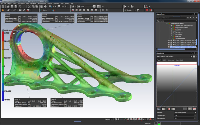
Using a combination of CT scanned data and engineering analysis, you can validate the performance of your parts against FEA style simulation
VGStudio Max – FEA-based part validation
With your CAD part and your scanned part in place, the next stage is to use simulation tools built into VGStudio Max to set up an FEA-based validation simulation on your scanned data. Loads and constraints are applied to the model, using the CAD reference for location.
The system then applies those boundary conditions to your manufactured part, taking into account the actual geometry of the part, and also includes any internal defects or voids. Stress concentration can be visualised and the effect of any flaws or pores evaluated — not on an idealised model, but the actual part.
Stress flow lines can also be plotted and visualised. This is key for many parts, but when you’re dealing with intricate lattices or generatively designed forms, particularly where a build error might mean a weakened strut in your form, it can be critical to the pass or failure of your part under loading.
To enlarge image click here
In conclusion
AM holds many benefits, particularly when it comes to metals. The ability to develop forms that would be difficult to manufacture using traditional machining or casting processes means that there’s potential to save weight or provide additional functionality.
While the ability to produce those forms is gaining interest, there’s also a need to fully integrate those classifications of parts into the full production life cycle, which always requires some form of inspection.
After all, if we’re producing sophisticated forms that save material and mass, we’re typically reducing the factor of safety involved or rather relying on less material to provide the required factor of safety.
If we’re reducing mass it also means that the material in our parts needs to be consistent and perform exactly as expected. As a result, we have narrower margins for error during manufacture — any flaws, imperfections or voids in those forms could have a catastrophic effect on the part under loading.
So it’s essential that we inspect the full form of an additive manufactured component — something that can only be done using a noninvasive technique like CT scanning.
This is where a system like VGStudio Max comes in. We all know that the manufacturing process is rarely perfect — it’s all about managing those imperfections to achieve consistent parts that perform as required. To that end, we need a greater understanding of the structure and performance of our parts when in use.
That is as true of traditionally manufactured parts as it is of those produced using additive manufacturing techniques.
What’s different about AM components is that, by their very nature, they are more difficult to measure and validate. Imagine a part that weighs 50 per cent less than a traditional part but features a microlattice structure to achieve the same stiffness and/or strength.
Traditional inspection methods can’t accommodate those types of structures and due to the wide variety of influencing factors, there’s huge potential for errors to occur in those micro structures.
When dealing with these types of structures, failure in one or two struts might result in a part that still performs as required or it might be localised enough to cause failure under loading. All of which means a part failure caused by a couple of voids in those struts that possibly wouldn’t be found until it’s too late.
Using a combination of intelligent design, advanced AM technology (though not purely restricted to AM) and comprehensive post manufacture CT-based inspection, any errors can be evaluated on a per build basis.
This way we stand a much greater chance of being able to build more efficient forms that solve engineering challenges in new and novel ways that take full advantage of new tools and technologies — all the while being able to validate the resultant parts.
Volume Graphics has a long history of working with voxel-based CT derived data and it’s good to see them applying that wealth of knowledge to solving engineering and production challenges that are going to come increasingly to the fore.
| Product | VGStudio Max |
|---|---|
| Company name | Volume Graphics |
| Price | on application |


