We review Solidworks 2020, and ask whether it still boast the innovation that set it apart from the competition for so many years? Jeffrey Rowe reviews the latest update
There was a time when a large portion of the so-called mid-range CAD market was dominated by Solidworks.
Its features, capabilities, continual improvements and user community were without equal and, quite honestly, the envy of many of its competitors. That ship may have sailed.
The world has changed as competitors have matched, and in some cases surpassed, what Solidworks offers from the standpoints of capability and cost (both upfront and ongoing cash outlays).
There’s no denying, though, that in many market segments, such as production machinery and consumer products, Solidworks is still the design product of choice and king of the hill. But with a change of philosophy and direction coming from its parent company Dassault Systèmes, will Solidworks continue to enjoy the support of its loyal user base – or will it become just a part of Dassault’s bigger 3DExperience marketing scheme?
That remains to be seen, but let’s have a look at Solidworks 2020, to see if it is still as compelling as it once was.
What’s new – really?
This review covers Solidworks Premium 2020, the flagship in the desktop Solidworks product family, and includes 3D solid modelling, large assembly design, sheet metal design, weldments, plastic and cast part design, mould design, electrical cable harness and conduit design and piping and tubing design.
Of course, all of these areas can’t be covered here, but I’ll focus on what I think is really new and improved and would benefit the majority of Solidworks users. With just a couple exceptions of products that are optional and come at an additional cost, I will cover features and capabilities available in Solidworks Premium 2020.
First: performance. Regardless of vendor, has there ever been a release of CAD software where improved performance (along with drawings) was not touted as a new and major aspect? The answer is no, and Solidworks is not deviating from that practice with the 2020 release.
Assembly performance is optimised for some tools and workflows, so full rebuilds of assemblies or graphics occur less often.
Most assemblies and drawings that were saved in a previous version open nearly as fast as those saved in Solidworks 2020.
You can use lightweight components and drawings without needing to convert them to the current version.
Previously, some assemblies and drawings that you did not save in the most current version took longer to open and save. This was particularly true for assemblies and drawings with reference components in multiple configurations.
A continuation of a performance enhancer in Solidworks 2020 is Large Design Review, which lets you open very large assemblies quickly for conducting design reviews.
Because it is intended primarily as a means for fast reviews, if you want to ensure that all parts have properly updated, you’re better served by opening an assembly as lightweight or fully resolved.
For quickly opening part configurations, Quick View mode lets you specify a particular configuration to open. Before opening a configuration, you need to specify which configurations are available in Quick View mode. To determine which configurations are available to other collaborative users, you need to open the part in Resolved mode first. Quick View is also available in eDrawings.
Sketching
Virtually all new models begin with sketches and Solidworks 2020 has a couple new twists on sketching. You can apply torsional continuity constraints/relations between splines and any other sketch entity in 2D sketches that results in G3 continuity.
Two curves that satisfy the same conditions as the ones having curvature continuity, and in addition have the same constant rate of change of the curvature, are said to have G3 or torsion continuity.
The sketch entities must share an end point, and these relations create a smooth continuity at the end point and apply equal curvature and an equal rate of curvature to the sketch entities.
You can apply torsion continuity relations to a spline, style spline, or generic spline and the following sketch entities: spline, arc, conic or elliptical arc, as well as model edges that are linear, circular, conic, parabolic, elliptical or spline-based.
The torsion continuity relation requires that the starting spline is a style spline B-spline with at least nine control vertices. If the spline does not meet these requirements, a prompt displays to caution you to properly convert the spline.
With the new silhouette entities capability, you can create multiple sketch entities by projecting the outline of the bodies in a part or components in an assembly onto a parallel sketch plane.
Silhouette entities create parametric sketch constraints on the model. You can use silhouette entities when you use Sketch and 3D Sketch On Plane. Silhouette entities can also be used in Section View mode.
Flexible parts
For experimenting with designs in nearreal-world circumstances, you can define a part component as flexible to drive the geometry of flexible components by the assembly geometry as an assembly reference with components in different states or conditions.
For example, you can model a spring in the context of an assembly, where the length of that spring is driven by an external reference in the assembly.
You then insert the spring into a second assembly, where the spring appears with an out-of-context reference.
You can use the Make Part Flexible tool to remap the out-of-context reference to the second assembly. As a result, the spring is driven by the second assembly without affecting the nominal length of the spring.
The custom and configuration-specific properties of the flexible component are the same as these properties in the component’s nominal state. Properties show the value from the nominal state.
Select Use Mass Property From Rigid State to apply the mass properties of the component in its rigid state to the activated flexible component. The flexible component will update dynamically when an external reference changes.
In order to change a component from flexible to rigid, you select the part and click Make Part Rigid in the context menu. The remapped external references are deleted and you will see that the component returns to its nominal state.
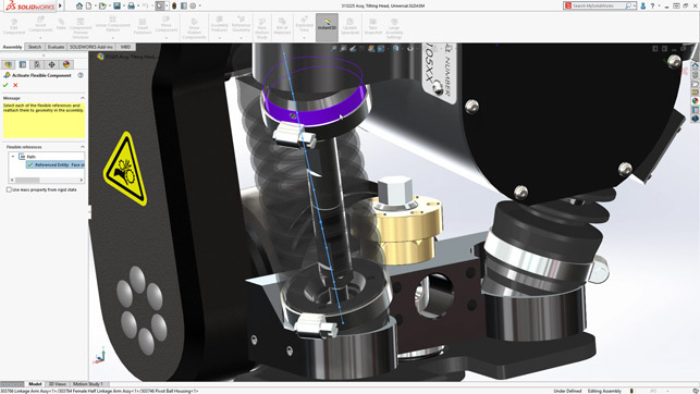
Make Part Flexible is a new capability that allows you to display the same part in different conditions in the same assembly
Solidworks MBD
Although it’s a separately purchased product, I want to touch on Solidworks Model-Based Design (MBD), because it’s become a relatively hot topic, especially when we are thinking about collaborative design.
The 3D PMI Compare tool now performs a more thorough analysis of reference dimensions, in order to identify more similarity scenarios based on geometry.
It also checks annotation notes, reference dimensions and geometric tolerances.
In assemblies and parts, annotations appear in subfolders under the Annotations folder in the FeatureManager design tree.
From the folder, you can sort the annotations and highlight them in the graphics area. When you select an annotation in the FeatureManager design tree, it is highlighted in the graphics area.
Annotations are critical for MBD to succeed and these new capabilities provide good support for implementing MBD practices.
Meshes and surfaces
With the help of artificial intelligence, according to the company, you can add references axes and reference planes to a graphics mesh body or a mesh BREP body by selecting facets, facet fins, or facet vertices.
You use facets as planar references, facet fins as linear edge references, and facet vertices as point references.
Reference axes and reference planes are useful when you create a model based on a graphics mesh body or a mesh BREP body and you want to add geometry. This is available for both parts and assemblies.
Before adding reference axes and reference planes, you have to turn on the Selection Filter toolbar to select facets, facet fins (edges) and facet vertices in the graphics area.
For Cylindrical/Conical Faces in the Reference Axis PropertyManager, you use Paint Select Facet or Tangent Select Facet to select groups of facets.
For Solidworks 2020, more new features support mesh BREP bodies, including shell, fillet, draft, chamfer and others.
The Insert menu includes a submenu for mesh-specific tools, such as Convert to Mesh Body and Create Surface from Mesh. I found this latter mesh tool especially useful and accurate.
The Decimate Mesh tool, meanwhile, reduces facet count in graphics mesh bodies. A lower facet count makes it easier to modify a graphics mesh body.
You can reduce the facet count for an entire body or a group of facets in the body.
To select a group of facets, you can use the Paint Select Facets tool or the Tangent Select Facets tool.
While useful for meshes, on the down side, this tool does not support mesh BREP bodies.
If you often deal with surfaces, another nice addition to Solidworks 2020 is the new Offset Surface tool that identifies faces on a surface it cannot offset, and lets you create an offset surface without them.
When the tool starts to create an offset surface and encounters failure, it lists faces it cannot include in the offset surface.
Those faces would probably fail because a) their offset surface includes an area with a radius of curvature that is less than the offset distance; b) they self-intersect; c) they conflict or interfere with nearby faces; and/or d) the offset surfaces are not connected, for example, because the offset has broken references or is based on faces from multiple parts.
If you click Remove All Failing Faces in the PropertyManager, the tool creates an offset surface with gaps caused by removing the failed faces.
You can repair the gaps by manually adjusting the offsets of the failed faces and adding them back individually into the offset surface.
An alternative if the tool fails is to reduce the offset distance and run the tool again.
Until now, in previous versions, the Offset Surface tool failed when it could not create an offset for one or more faces of a surface.
The tool did not identify which faces caused the failure, which made the offset surface difficult to complete.
New analysis tool
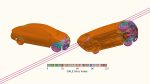
A new analysis tool in Solidworks 2020 is Body Compare, for comparing two groups of bodies that are co-located in the same part or assembly. For example, you can compare a CAD model against a scan file, mesh file or another CAD model.
For models that you reverse engineer, you can use Body Compare to compare these models to the original scan to find differences. For manufactured parts, you can scan the part and compare the scan to the source CAD model.
The deviations display on the source body to indicate where the two bodies do not match. When creating a body, select Unmatched color in the Body Compare PropertyManager to show where the source and the compare bodies do not match.
After you create a body compare analysis, the analysis remains on display in the graphics area. To close the analysis, rightclick in the graphics area and click Body Compare. To modify the analysis options, right-click in the graphics area and click Body Compare Properties.
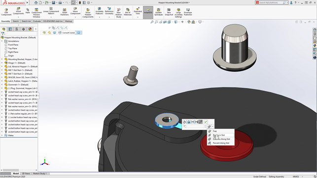
To speed assembly design, the Quick Mates Context Toolbar now provides the following mates: lock rotation, flip mate alignment, limit distance mate, limit angle mate, slot mate and width mate
3D Interconnect
Solidworks 2017 brought a welcome change for data translation: 3D Interconnect. It replaced dated and limited translation capabilities with new technology and workflows for working with third-party native CAD, including Catia V5, NX, Creo, STEP and others.With 3D Interconnect, you can insert proprietary CAD data directly into a Solidworks assembly without converting it to a Solidworks file. It’s also possible to open the proprietary 3D CAD format in Solidworks with its associative link to the original part.
If you update the proprietary CAD data in its authoring application, Solidworks also updates and maintains all downstream features created in Solidworks. You can also, of course, break the link of the inserted part file with the original part file.
In Solidworks 2020, 3D Interconnect supports importing BREP data from DXF or DWG files. In the DXF/DWG Import dialog box, under Import to a new part as, click 3D curves or model. The software imports the BREP data from the DXF or DWG file.
You can edit features, break links, and update models on the imported body. This new support is especially useful for shops that also have AutoCAD in-house or work with outside vendors that use it.
Product data management
This is the capability that just about everybody loves to hate, but one that just about everybody uses.
Solidworks PDM loads data in the background, which improves the browsing responsiveness. Browsing folders that have a large number of files is faster in Solidworks 2020, due to faster database queries for custom columns, as well as background loading and incremental loading of the data.
You can define conditions on the state of immediate child references to control the parent file transition. When you define conditions, you can transition the parent file only if its child references are not selected for transitioning with the parent file and are already in a state that meets the defined condition; or selected for transitioning with the parent file and, after transition, are in a state that meets the defined condition.
These conditions help avoid situations such as approving an assembly when the referenced parts are not approved or if/when an assembly uses obsolete parts (never a good thing).
Drawings
Even though it’s almost the year 2020, what CAD review would be complete without at least a mention of drawings?
Available for drawings saved in Solidworks 2020, the new Detailing mode lets you add and edit dimensions and annotations within a drawing, but the model data is not loaded.
You can use Detailing mode to open large drawings quickly. The model data is not loaded, but you can add and edit annotations within the drawing.
It is also useful if you need to make minor edits to drawings of large assemblies or drawings with many sheets, configurations or resource-intensive views.
In this mode, you create dimensions and annotations just as you would in Resolved mode. However, there is an exception: you cannot create dimensions or annotations that require model information, such as hole callouts, cosmetic threads, or links to model properties.
If a drawing is open in Detailing mode and you change and save an associated part or assembly, then an ‘out-of-date’ message is displayed.
The Resolve Drawing tool always appears in the CommandManager, so you can resolve the drawing at any time. You can save your changes to the existing drawing file without exiting Detailing mode and saving in Detailing mode does not create or require a special save format.
Some of the things you could do in Detailing mode include changing the position, rotation and labels of drawing views; copying or cutting drawing views and pasting them onto the same or other sheets within the same drawing; inserting sketch blocks; and saving as a PDF/DXF file, or print as a PDF.
It’s worth noting that this mode is not available for detached drawings and has a couple other limitations, such as the inability to create new drawing views, centrelines, centre marks or hatching, and you cannot use the Undo tool (which could prove frustrating).
Even with its limitations, however, the new Detailing mode could on the whole be classified as a significant enhancement.
With Solidworks 2020, you can draw markups with a mouse on non-touch devices or stylus on touch devices, display bounding boxes for mark-ups, create mark-ups in drawings, and use the context toolbar to access markup options. This new mark-up functionality will likely prove popular for design reviews.
As a final quick note on the topic of drawings, you can upload .stl files from eDrawings to the 3DExperience Marketplace|Make for manufacturing and also for finding vendors to provide manufacturing quotes.
Speaking of the 3DExperience, there is a SolidWorks Connector for uploading Solidworks PDM data to Enovia, Dassault’s PLM platform. This is the first of what will probably be several direct pipelines to other Dassault brands and 3DExperience in the future.
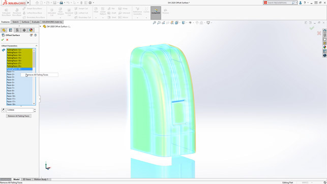
The Offset Surface tool now identifies faces on a surface it cannot offset, and lets you create an offset surface without them
Final thoughts on Solidworks 2020
Although Solidworks 2020 does indeed offer a number of improvements, primarily in performance and the connection to Dassault’s wider 3DExperience, I would not exactly classify this release as a blockbuster.
Instead, I view Solidworks 2020 as the first major step towards Dassault’s grand vision of the 3DExperience and, to a lesser degree, the legacy Solidworks user.
Will current Solidworks users literally buy into this notion and upgrade to the 2020 release? That remains to be seen, but I am sure a good number of users will be questioning the direction of the parent company, as well as asking more specifically whether this latest release meets with the short- and long-term goals of their organisation.
Don’t get me wrong, I’ve been a fan and proponent of Solidworks since the beginning in 1995 and I have been working with it since 1996.
The thing I am most inclined to question are the increments of improvements we see in the system. For many years, the incremental changes were huge. More recently, it seems they have become smaller and smaller. That’s not to say that improvements are insignificant. They’re just not as compelling and for me, they’re lacking the ‘wow factor’.
On the plus side, Solidworks is unquestionably a mature and stable product, which is a good thing.
So is Solidworks still the CAD product to beat? In some cases, yes; in others, no. What will happen to this workhorse CAD in the future is the subject of a great deal of ongoing speculation, but the fact remains that it is still a dominant and very capable design tool for a large portion of the electromechanical design, engineering and manufacturing markets.
| Product | Solidworks 2020 |
|---|---|
| Company name | Dassault Systèmes |
| Price | on application |