
Creo 6 – When it comes to maturity in the 3D design system industry, it’s hard to beat Creo on track record. We look at the latest update to PTC’s flagship product and find that it is still making plenty of room for true innovation
In the last few years, PTC’s Creo has been through something of a renaissance. To those who have followed PTC’s move into the world of the Internet of Things (IoT), it might seem that the company’s heritage in the business of design and engineering has been forgotten, but if you dig a little deeper, the reality is a little different.

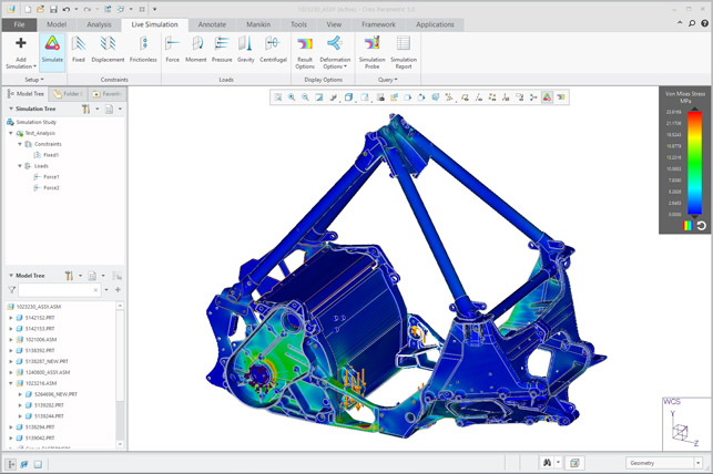
Creo 6 sees the introduction of a new simulation module, Creo Simulation Live, based on the Discovery Live technology from Ansys
Yes, there has been a shift in focus inside PTC beyond the world of 3D CAD and PLM, but it’s important to note that there’s a pretty rich set of synergies between this traditional operating area and the brave new world of IoT, augmented reality (AR) and virtual reality (VR). After all, it’s all very well having a digital twin of your inservice equipment, but if you don’t have the engineering data about it to begin with, you’re already behind.
So, shall we explore where PTC is at with Creo 6.0? There are four key themes in this release. While three of these focus on specific areas of functionality or on industry topics, the first we’re going to look at is far more general and applicable to almost every user.
Creo 4 and 5 saw PTC start to address the user experience and bring certain areas up to speed with the expectations of modern users. While Creo will never take on the full Windows ribbon UI, there’s been a lot of work done to make the software seem more familiar to new users, as well as to add in some new tricks for long-time users.
One such area is the mini toolbars introduced over the last few releases, which have since spread to more areas of the system. For Creo 6, these pop up during feature definition and let you define the parameters for your current operation directly at the cursor.
Related to this are the dashboards that contain all options and parameters for your current operations, usually found at the top of the modelling window. These have been expanded a little to allow more information to be squeezed into multiple rows, which is useful for keeping things compact.
Another nice tweak can be found in the model tree. Now, when you activate a part or sub-assembly within an assembly, other components in that assembly will grey out, to show where you are in the product structure. If you’ve activated a part or subassembly a couple of levels down, it’ll show this by keeping the higher levels solid.
Lastly for general operation updates is that each operation links directly to a page in the help system. There’s been a worrying trend seen in some software for help systems to become an afterthought, forcing users to rely on community forums rather than the vendor putting in the hard work, so it’s nice to see some attention paid here to something so vital.
Before we get into the meat of the Creo 6 release, there are also a couple of other updates that might seem small, but which will be a real boon for those using these tools or workflows. One example is seen when projecting datum points between sketches or onto surfaces: where previously performing this task might have taken a couple of operations, it’s now been consolidated into a single command.
There are two new modelling feature options. These relate to creating volume sweeps with helical paths (a common topic in many recent CAD system updates) and giving users greater control over drill tip angle when building hole features.
The last generally applicable update to mention is the addition of new emissive material in the Creo Render Studio module.
As users will know, this is based on Luxion’s KeyShot, but is adapted to run directly in the Creo interface. There’s no physical measurement of the emissivity (in lumens), but it’ll let you dial things in quickly.
Augmented reality
Ever since PTC got bitten by the IoT bug, company executives have talked a lot about how the company’s solutions bridge the gap between physical products and their digital representation, in whatever form that takes. An interesting offshoot from this is that PTC has acquired and built out a whole bunch of expertise in AR, which allows you to take your digital model and view it in the real world using a variety of devices. Creo 4 introduced the ability to generate these AR assets from a Creo session and then share them, but there were some restrictions around how you could control that data.
In the intervening releases (both large and point releases), this capability has been both expanded (to now include Creo Elements Direct and Windchill) and finessed.
For Creo 6, PTC has added not only greater control over access to the assets you create, allowing you to restrict access to authorised users people and remove it when needed, but also making sharing them easier. For example, you can now generate an invite email to multiple folks at once. In terms of the data you can create, previous releases restricted you to just five experiences, but this limitation has been removed allowing you to create ten.
Lastly on the AR front, in addition to existing support for handheld devices (smartphones, tablets and so on), PTC has also released support for Microsoft’s HoloLens device. What’s interesting here is that, unlike most HoloLens applications, which require a compiled experience to be installed on the device, AR experiences can be streamed to the headset using PTC’s Vuforia app, making it both more efficient and secure.
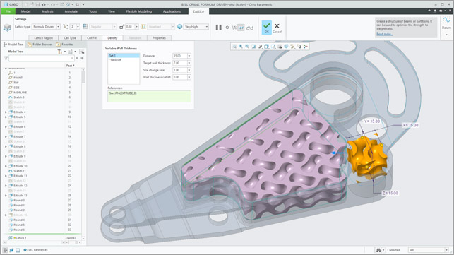
New formula driven lattice controls afford you greater control over the design and placement process – such as variable thickness, as shown here
Simulation-driven design in Creo 6
Now, let’s talk about something really exciting. We’re all aware of CAD-integrated simulation tools. Creo, just like almost every other 3D design and engineering system, has its own built-in set of simulation tools; in this case, Creo Simulate. This is based on the rather aged Pro/Mechanica set of tools that will be familiar to many Pro/Engineer users out there, albeit updated and presented in the Creo interface style.
It follows the same workflow as most of these tools: take your 3D model, remove inconsequential features to make meshing easier, mesh it, add loads and constraints – and then wait. Maybe you’ll wait for 10 minutes, maybe six hours, to get your result.
Rinse and (frankly) tediously repeat – this is how it’s always been done.
Then along came Ansys with its Ansys Discovery Live (ADL) technology. Using the combination of a brand-new approach to computation of both structural and fluid flow problems and today’s super-powerful GPUs, it can deliver reasonably accurate results in near real time.
So what does this have to do with PTC?
The simple answer is that it has licensed the technology from Ansys and has begun the process of integrating it into a new module called Creo Simulation Live.
The system works just as you would expect if you’ve seen ADL at work. You take your part (or assembly), apply your loads, constraints and materials, and the system delivers the results almost instantly.
In terms of what you can do with this, the system currently supports structural linear, thermal and modal simulate studies (and the CFD portion will come soon, I’m told). Because this is built into the design environment and not a separate application, users can now continue to evolve their design, while having Creo Simulation Live providing continuous, live updates of simulation results.
In terms of using assemblies, the system assumes full rigid contact between all parts.
Also, as with ADL, you have control over the fidelity of results, allowing you to move between super-quick but coarse results, and higher resolution results that take a little more time.
While we’re not able to discuss pricing (PTC declined to provide list pricing), I think we can safely assume that this module is going to be in the same region of ADL, so around the five grand mark. Also worth noting is that PTC has made this available not only to Creo 6 users, but also as part of maintenance releases for both Creo 4 and 5. There’s no big differences between the different versions, except that in Creo 6, you can add in more detailed probes to grab data from your results.
Lastly, if you’re a Creo Simulate user, any studies and load cases you set up in Simulation Live can be reused in Creo Simulate to save you a bit of time, if you need to carry out more in-depth studies.
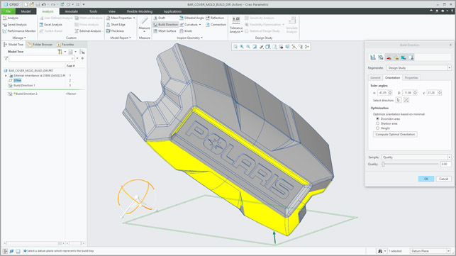
The new Build Direction Analysis tool will find the optimum build orientation based on your requirements, but won’t account for where you need the best surface finish
Additive manufacturing in Creo 6
PTC has introduced a set of additive manufacturing focused tools over the last few releases, from build chamber preparation and lattice design tools in Creo 4, to the introduction of support structure generation in Creo 5. For Creo 6, the work on lattices has developed a fair old bit, with not only more control over the process, but also an increase in the types of lattice you can create.
In terms of new types of lattice, you can add both gyroid lattices and stochastic lattices (these are the sort of randomised lattices you might have seen, based on Voronoi mathematics). The latter are useful for a variety of engineering applications, from filter design and light-weighting to more niche areas such as medical device design. It’s worth noting that these are sized at the time of creation and are consistent across the lattice.
It’s also possible to model up your own lattice cells. Of course, these need to be based on a repeatable and tillable cube, on all six sides of that cube.
Once lattices are built, there are new controls over how the geometry transitions from lattice to the surround geometry/wall of the model. There is also an interesting set of tools to add additional supports into a lattice to assist with the build process, so that it is self-supporting and supports the surrounding geometry. (Consider, for example, internal walls in a part, where additions to the lattice might eliminate the need for additional support structures.)
There’s also a new tool called Build Direction Analysis. This works in a similar manner to Draft Angle Analysis already available in Creo, but focuses on ensuring that you can build your part. Obviously, this depends on the machine, material and process (none of which is accounted for in the tool).
It works purely on the geometric aspects of the system. In the first instance, it identifies which areas are going to need support structures, then allows you to optimise the orientation of your part. This latter tool is particularly useful, as it will carry out a series of optimisations to find the best orientation, though it’s worth noting that this doesn’t account for which part of that geometry you want to be a-surfaces and achieve the best surface finish.
The new optimised orientation can then also be directly fed into the lattice feature to allow your lattice features to be oriented based on build direction. This process helps to remove the need for addition support structures and the time-consuming post processing work needed to remove them.
Lastly on the additive manufacturing front, there are some interesting additions in terms of export options. As you’ll be aware, STL has been the standard format for 3D print-focused communications for decades now. It sucks, and it’s certainly not particularly intelligent, but it at least works fairly reliably.
For Creo 6, PTC has extended its support for the more modern, more intelligent 3MF format. This will retain colour and material information when present, but in more recent definitions, it has some very useful support for lattices that makes the communication of such heavy data more efficient.
There’s also support for CLI (which stands for Common Layer Interface) output; this is a method for communicating additive manufacturing geometry as a series of slices. The reason this is so useful is that Creo is generating slices from real CAD geometry, rather than a tessellated mesh, so definition should be more precise.
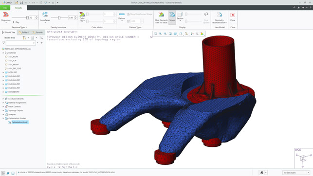
Although Creo 6 sees some advances in topology optimisation, users can expect a great deal more work on this front in Creo 7, as PTC’s recent acquisition of Frustrum begins to bear fruit
Topology optimisation
To close out this look at Creo 6, let’s talk about topology optimisation – something of a hot topic of late. Creo 5 gained some of these tools to help with lightweighting and optimisation, used in the manner you’d expect: you develop a domain space, add in the features you need to retain, loads and constraints, and have at it.
What PTC already handled nicely was the final part of the process, which saw typically mesh-based, quite coarse results turned into a pretty decent surface model, making integrating those forms into downstream processes more efficient.
What’s new for this release is that you’re now able to include assembly geometry into the process. It’s important to understand how this can be used and the assumptions that the system makes. It assumes, for example, that the whole assembly is in full rigid contact and is used to help position loads. It does not compute how loads on other, non-optimised parts pass through to the optimisation domain. Think of it as a remote load on your domain, which really helps you assign loads more accurately.
Of course, we can’t discuss topology optimisation without mentioning PTC’s recent acquisition of Frustum and its optimisation technology. None of those is included Creo 6, so we’re likely to see it in the next major update.
In conclusion
The 3D design software market is in a strange place at the moment. There are a number of brand-new systems making a lot of noise, but which don’t seem to be achieving a huge amount of headway, while some market leaders are refocusing on new initiatives and industries.
This puts PTC in a very strong position with its Creo product. It’s mature enough to be able to cope with the serious engineering heavy-lifting that many new systems can’t handle, but PTC is also clearly investing in development in order to build in brand new functionality at the same time as revitalising more mature toolsets.
Creo 6 is a pretty rock-solid release for those who are keeping up-to-date with their software releases. For those who have skipped Creo 5, it’ll give them a good impetus to catch up.
For those outside of the PTC fold, looking in, I would suggest that Creo is as worthy of your attention and investigation now as it ever has been. There is some true innovation here, backed up with three decades of development, fine-tuning and exacting use by some of the most advanced customers on the planet.
| Product | Creo 6.0 |
|---|---|
| Company name | PTC |
| Price | on application |


