If you’d listened to many of the cynics over the past few years, you would think that parametric CAD (history based) and SolidWorks in particular would be dead by now.
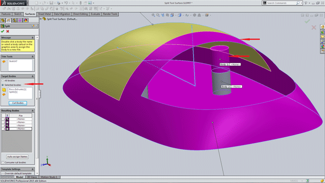
SolidWorks 2015 now extends the power of the ‘split’ tool that’s been around for a while to now work with surfaces as well as solid bodies
However, with SolidWorks 2015, we once more see the continuing development of the product. With this release, the team has managed to strike a fine balance between big new features, continuing improvements to existing features and a huge bonus with the reduction of file size (on disk).
There is also a greater continuity and a very familiar workflow across the program.
My background is in manufacturing or, more correctly, I have spent my entire working life in manufacturing. I’m mainly a “Parts and Assembly” man, perhaps even a little old fashioned in how I work.
My method of modelling tends to relate to how we manufacture. So, for me it is the daily use features that I find to be of the greatest benefit. Anything that reduces mouse movement (or in my case thumb movement on the trackball) or decreases the number of times that you need to hit the mouse button is always a good thing.
With those thoughts in mind, let me share what I believe to be some of the better enhancements from the release of SolidWorks 2015, a Beta version of which I’ve been using for the past few months.
Sketches
The fundamentals of all models are sketches. The pick of the new sketch features would have to be midpoint sketch. It doesn’t take long to work out that there is an advantage to having a model with a line of symmetry.
The simplicity of the midpoint sketch is being able to create a line that is symmetrical from the midpoint. The ability to do this without the need of additional references should make this one of the most adopted features.
It also brings it in line with the centre rectangle tool. The rectangle tool has also received some additional functionally. Centrelines to rectangle have now been added to all rectangles, not just the centre rectangle tool. Where the centrelines were once only from the corners, they now have the option to be added from the Midpoints.
The sketch tool that I feel has the most potential is the new segment feature. Not only is it an interesting feature but one that will also reduce the need to add numerous additional construction lines and equal references.
Any line (or arc, circle) can now be divided into equal segments with this new feature. Either with a number of sketch points or a number of sketch segments. Sketch points divides the line with an equal number of (stated) points and adds those segment points. Sketch segments not only divides the line up by the number of (stated) equal segments but also splits the line into that number as well.
Features
It wouldn’t be 3D without Features. For as long as I can recall, there has always been the ability to ‘cut extrude’. Through All (in both directions) using an Open Profile Sketch, as long as the sketch at least intersects the edge or was beyond the part. Now we see the expansion of this feature to include control over the direction for Through All.
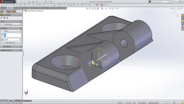
Now you can extrude or cut-extrude with an open profile — letting you get to the result you want without additional features or work
However, its real party trick with SolidWorks 2015, is the addition of being able to cut extrude to a dimension using an open profile sketch. The sketch as always needs to intersect the edge or extend beyond the part — I see this as a great move! No longer will there be the need for additional lines or extra context sketches just to close the sketch.
More power to split
I love the Split Tool. There, I’ve said it (unashamedly), and what’s not to love about it? A most versatile tool to be used for whatever reason you need to make a part into multiple bodies. Whether that is to be used in conjunction with direct edit tools (and separate bodies) or to save out individual bodies. It is the tool for many occasions.
Its only limitation used to be that it could only be used with solid bodies. When working with surface bodies, there were always workarounds. You could use a split line, delete a face, or zero offset a face, or trim something or do this or do that.
Either way, it was a different work flow that you would otherwise require than if you were working with a solid model. SolidWorks 2015 allows the split tool to be used in the same way with surfaces as you would with solids.
But wait. There’s more; the split command also has the ability to simultaneously split both surfaces and solid bodies to create multiple bodies all within the one feature.
That certainly has increased the functionality of the split tool with its ability now to reduce time and features within a Surfacing environment. More importantly, it will assist those that are starting to transition from solid modelling to surface modelling, by introducing a common workflow between the two.
I also have a deep affection for PEM fastener when using sheet metal parts. For those not acquainted with PEM fastener, they are fixings that are pressed in a predefined hole. The fitting displaces some material, forcing it into an annular recess in the fitting.
A serrated clinching ring prevents the fitting from rotating, making the fitting a permanent part of the sheet metal. They require an accurate sized hole that is matched to the required fitting. I use M6 self clinching nuts in a majority of our sheet metal mounts and various brackets.
I don’t have any trouble remembering that they require an 8.75mm diameter hole. However, that is not the case with many of the other types of PEM fasteners or different size fittings.
This is no longer an issue with SolidWorks 2015 as we see PEM fasteners corresponding holes have now been added to the Hole Wizard. It is now just a case of selecting the type and required size of the PEM fastener and the Hole Wizard will insert the correct diameter hole to the part.
With this enhancement, it also rounds out the software and ties it in with the PEM fastener in the Tool Box.
Assembly
Creating assemblies is all about mates. In the majority of cases that would requires three mates to fully define the parts. That equates to many, many mouse clicks.
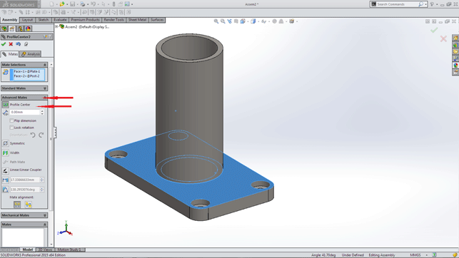
Assembly mates can now be placed at the centre of a sketch
For those who manufacture and assemble using parts that have geometric profiles (rectangular, circular and the like), the new Profile Centre Mate has the potential to eliminate much of that.
Let’s say you are looking to mate a post to a plate with a centre alignment. It is now just a case of selecting the end face of the post and the face of the plate. Then, by selecting the Profile Centre Mate, it will automatically centre align the two components and complete the mate.
The most interesting of the new mates would have to be Width Mate. It uses reference geometry to drive the mate constraints. If you need to position a component on a linear rail (or a post or similar), the reference geometry would be the two parallel ends of the rail.
The component can then be positioned by its reference geometry (the Tab Reference) and the required constraint. ‘Free’ if you require the component to slide from end to end of the rail. ‘Centred’ if it is required to be equidistant from the rail ends. ‘Dimension’ will allow a distance from (either) end of the rail. Perhaps the most interesting is ‘Percentage’ that allows the component to be positioned by a percentage of the rail.
Productivity
A couple of very interesting productivity features have been introduced with SolidWorks 2015. Simple and efficient is dynamic reference visualisation which provides a graphical reference in the feature tree (both for parts and assemblies).
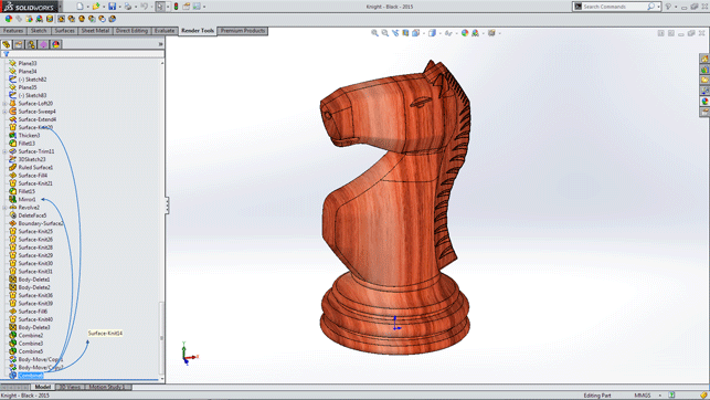
The visualisation references are now shown dynamically
As you hover over a feature that has a reference to other features, an arrow (or a series of arrows) will point to all of the features that are referenced.
I only need to have one version of SolidWorks installed on my computer at any time.
There are many who are required to work with multiple versions for reasons of file compatibility. Previously there was no simple way of knowing what version the file was.
With SolidWorks 2015, in either SolidWorks Explorer or Windows Explorer (in the detail pane), you will now see which Version (Identify File Version) the file was last saved in. Some people will be very happy about that.
Smaller files
Now, here is the added bonus with SolidWorks 2015 — reduced file size. I had heard about this much earlier in the year, however, the real significance of this took a little time to really sink in.
Personally, on a small sample size of files, I’m seeing an average reduction in the size of the file (on disk) by around 48 per cent.
You could argue that file storage is relatively inexpensive these days. Whilst that may be true for individuals, with consumer level disc it’s a different case when moving into data archival, enterprise storage, storage replication (as with Enterprise PDM vaults) and network transfers used within larger corporations.
If you need one, and only one single reason to upgrade to SolidWorks 2015, then I believe this would have to be close to it.
Conclusion
These were just a few small examples of some of the 200+ new features and enhancements within the SolidWorks 2015 release.
That’s not even having a chance to look into the enhancements to Drawings and Detailing, which have the most pages (per Chapters) in the ‘What’s New SolidWorks 2015’ document. Nor within some of the more specialised areas of the product, such as SolidWorks Enterprise PDM which now sees the introduction of a web based mobile client.
Dassault Systèmes SolidWorks keeps providing the time and money required for the ongoing development of the SolidWorks product. The development team has again delivered with this release, innovative new features, especially in the areas of Sketches and Mates (in Assemblies) along with the refinements to many of the current features.
It is these refinements that have provided much more continuity and familiarity across much of the product.
SolidWorks continues to have its capabilities expanded and enhanced. As a CAD package it is as relevant now as it has ever been.
solidworks.com
Biography: Michael Lord

Michael Lord works as a design/engineer and is currently the manager at Trakka Pty Ltd, an Australian manufacturer of motorhomes and special purpose vehicles.
He has 40 years experience of manufacturing under his belt, 10 years of which he’s been a SolidWorks user.
He covers how he uses SolidWorks on his blog:
michaellord.me
Model-based design: Enabling 3D annotation and documentation
Since the 3D design tool industry began, vendors have been predicting the death of engineering drawings but, 30 years later, we’re still waiting.
One of the technologies that has emerged that might provide a clear route to removing the 2D drawing is 3D annotation.
The concept is this: Rather than disconnecting the drawing layout (both in terms of data and process) from the 3D model, the two are combined. All of the dimensions, notes, GD and T are added directly to the 3D model — those entities which define all of a part (all of a part’s (or assembly’s) characteristics that enable manufacture).
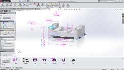
It’s an additional module on top of the standard bundle, but SolidWorks now has a full set of 3D annotation tools
They remain associative in case of design change and are stored inside the 3D model. The issue has not only been how that documentation is added to the model, but also how it’s reused, accessed and acted upon by those that need it, downstream from engineering.
The fact is that while traditional drawings are an extra, often lengthy, step in the process, they provide a clear way of organising and presenting this data.
Many vendors have been introducing these types of tools for some time. Siemens (In NX) and Dassault (with Catia) were first out of the gate and the mainstream vendors (SolidWorks, Autodesk, Siemens with Solid Edge) have been playing catch up.
For the 2015 release, SolidWorks gains an additional module, called SolidWorks MBD (Model-Based Definition), that gives users tools to define, organise, and publish 3D Product Manufacturing Information (PMI) and 3D model data in industry standard file formats.
SolidWorks MBD defines 3D PMI such as dimensions, datums, geometric tolerances, surface finishes, welding symbols, bills of material (BOM), callouts, tables, notes, meta-properties, and other annotations within SolidWorks.
| Product | SolidWorks 2015 |
|---|---|
| Company name | Dassault Systèmes SolidWorks |
| Price | On application |


