
From point-based systems to area-based scanning, Ralph Weir, chief executive officer (CEO) of Phase Vision takes a closer look at the wide range of 3D measurement technologies used in metrology and inspection 
Any company designing or manufacturing products with complex geometries will at some stage have a requirement to accurately measure either prototypes or finished products to ensure they meet design parameters.
The range of equipment available for this is ever-increasing, but is based around three main system types – point-based systems, consisting mainly of contact probes mounted on either a co-ordinate measuring machine (CMM) or measurement arm, and laser trackers; stripe-based systems, comprising mainly laser scanning systems; and area-based measurement systems such as white light systems.
The good news is that modern systems of each type generate results which are compatible with the latest CAD software. However, each system type represents a significant investment – although the expected outlay for each is in fact remarkably similar – so it is a decision which companies cannot afford to get wrong if they are to deliver to customer needs.
The eventual decision will depend on a number of factors including, but not limited to, measurement speed, the level of accuracy needed, the size of objects being measured, and the conditions under which measurement will take place.
For example, many items will expand as the ambient temperature increases, meaning measurements of the same item taken over a long period in an inconsistent temperature may not be completely reliable. This effect must be considered, and even where the measurement system itself is not affected by temperature, will limit the accuracy that can be achieved in real production environments.
Point-based systems
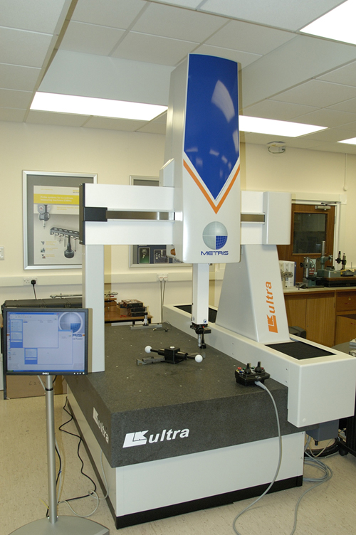
Co-ordinate measuring machines are the longest established three-dimensional measurement system having been originally developed in the 1950s in two-dimensional format, with the first three-axis models appearing from the 1960s.
Traditionally, CMMs have a granite base on which the product to be measured is placed, but this does restrict their scope, as no item which overhangs the base can be accurately measured, meaning even a very large CMM cannot be guaranteed to cater for all requirements.
Meanwhile, the lack of portability of CMMs means that the objects to be measured must always be brought to them, irrespective of their size, weight and fragility. They must also be operated in a temperature controlled environment – and the component to be measured must be allowed to stabilise at that temperature – in order to gain the accuracy of the CMM.
Measurements via a touch probe can be taken manually using a measurement arm, or with a CMM – which can be operated manually or programmed to move automatically.
Laser trackers typically consist of a spherical mounted retroreflector, containing a complex arrangement of mirrors, in front of a tracker. The measurement created is always to the centre of the sphere, rather than to the surface, while the sphere has to be moved manually each time
Point-based systems are highly accurate, down to 1 micron if required, but measure a relatively small number of points over the same amount of time compared with other system types. They are, therefore, less valuable when measuring items where a very detailed understanding of surface characteristics is required. However, point-based systems come into their own in applications where knowledge of the exact position of only a few points in relation to each other is all that is required.
A typical example of this is on aircraft wing jigs, which can be up to 20 metres long but may have only 30 to 40 crucial ‘pick-up’ points for where the wing ribs will be located. The same principle applies on large metal panels used in ship building to ensure they will fit together in the right places – both ideal applications for laser trackers.
The accuracy of point-based systems also comes into its own when measuring highly polished or reflective surfaces such as glass, with which laser or white light systems can struggle to cope. High specification lenses, for example, require very accurate measurement to ensure they are within tolerance.
Point-based systems also give an excellent idea as to the nature of holes, where a relatively small number of measurements can provide detail on diameter, and only a few extra measurements can start to determine the ‘roundness’ of a hole. For other systems, seeing into holes often remains a major challenge.
Where any form of system using a touch probe is not ideal, however, is in the measurement of items whose surfaces may be affected by coming into contact with the probe.
Clay models – still widely used in many industries – cannot by definition be measured using a touch probe as the surface will to some extent deform on contact. Here, a laser or white light system will have to be employed to deliver reliable results.
The humidity of the environment where the measurement is taking place must also be considered, as extended high humidity levels can impact on the performance of laser trackers, as can air currents.
Stripe-based systems
Stripe-based systems, such as laser scanners, can be either hand-held or mounted on an arm or CMM. They can usually measure ‘stripes’ up to 100mm long, taking many thousands of measurements – 75,000 per second is not uncommon – to rapidly create a number of point clouds which then have to be ‘patched’ together to create a complete representation of the object.
This ‘patching’ process can be highly time–consuming unless a high-specification system is used which can perform this process automatically – but in any case, the patching process introduces errors. For this reason, combined with their small stripe length, they are not best suited to measuring very large areas. Where they do offer advantages is in measuring where access is restricted, for example in car footwells.
Hand-held scanners are also well-suited to measuring longer items such as large turbine blades, where a measuring arm cannot be used as it is not long enough to scan the entire item without being moved.
The accuracy of laser scanners, however, relies heavily on the expertise of the operator. They are normally designed to be operated at a specific distance from the object being measured, and any deviations from this can impact significantly on the results achieved. Unfortunately, inaccuracies generated in this way are not always apparent at the time, meaning potentially significant costs further down the line.
Materials which either absorb light or are in any way able to be penetrated by light also do not lend themselves well to laser scanning. Materials such as casting wax and Rohacell – commonly used in the manufacture of carbon fibre – are just two examples. Effectively what happens to these materials is that the laser goes through the surface and measures points underneath it, again generating potentially misleading results.
Meanwhile, factors such as inconsistencies in laser focus, laser detune and laser speckle all mitigate against fast scanning of larger areas,
Area-based scanning
Area-based measurement systems such as white light scanners offer advantages over laser scanners in terms of the size of area they are able to measure at once – up to several metres across if required, although systems are available which are designed to measure very small objects as well – and their ability to operate across a range of environments.
As with laser scanners, a point cloud is again generated but there is less reliance on operator skill once the system is calibrated – consistent operating distance is far less of a factor – while the size of the area scanned greatly reduces the need to align patches.
These systems do, however, again pose some challenges in terms of patching in instances where the shape of the object cannot be relied upon to dictate the patching process – as is the case with large, smooth surfaces with few features, such as aircraft wings. In these instances, either a rotating table (for smaller objects) or photogrammetry targets in the form of adhesive labels will need to be employed to facilitate the patching process.
The presence of holes where precise detail is needed on depth and shape can also pose problems which are best solved by a touch-based system.
Again, white light scanners can experience problems when measuring highly reflective or light absorbent surfaces, although they do offer some measure of control here.
However, their speed and ability to measure a complete surface within a few seconds mean that white light scanners lend themselves ideally to high throughput environments and full integration into production lines where any inaccuracies or irregularities in manufactured products can be immediately detected and production stopped if required to allow rectification of the process.
This is something that is simply not achievable with point-based or stripe-based systems.
Meanwhile, their robustness and portability makes them ideal for even the most demanding environments – even dirty production areas, aircraft hangars and docksides.
Developments in each area of measurement continue apace and each system type will always have its proponents in each sector. For those companies with the ability to employ dedicated in-house measurement staff, or where accuracy of a just a few points is needed, a CMM or laser-based system may well be the best option.
However, the rapid pace of developments in white light scanning, its ease of use and robustness, mean it is more frequently becoming the norm especially where speed is of the essence or the measurement of large objects is required.
www.phasevision.com
An exploration of the rapidly-developing tools used in 3D meaurement
No


