
Vericut 9.1 has been launched by CGTech promising several new cutting-edge features, including AI optimisation, which aim to increase efficiency and empower users to do more in less time.
The CNC machine simulation, verification, and optimisation software is capable of simulating all types of CNC machining, additive, and hybrid manufacturing processes, operating independently, but also able to be integrated with leading CAM systems.
New visibility options, plus enhancements to toolpath optimisation, additive manufacturing, tooling and multi-tool stations, are just a few of the noteworthy features in this release.
“Vericut 9.1 continues to enhance the user experience through continued advancements with graphics and display controls, streamlined user controls, and more new capabilities and features than ever before,” said Vericut product manager Gene Granata.
“Version 9.1 also introduces a Learn mode for Force optimisation – a form of Artificial Intelligence for faster/easier NC Program optimisation.
“Using Learn mode, almost anyone can create highly optimised NC programs from existing programs, without having to reprogram them.”
New features in Vericut 9.1
Streamlined Optimisation with AI
The Optimize Control window has been streamlined to fit in a single window with no tabs. Relevant features become active in subsections depending on which Mode is selected.
A new Force ‘Learn’ mode is available, providing AI for optimisation.
In Learn mode, Vericut learns from simulating cutting, then automatically configures &and optimises tools for increased cutting efficiency and reduced machining times.
Enhanced Visibility
New visibility features have been added to the Project Tree and Vericut right-click convenience menus for components and models, enabling users to toggle between visible and invisible states, or to enable/disable 3-D objects for the simulation.
Users can quickly see unobstructed views of the cutting process and gain better access to the part by removing enclosures, models of sheet metal or shrouding, and other ‘in-the-way’ objects via Invisible or Disable actions.
New Visibility Options for AUTO-DIFF
Similar to the above, new features have been added to AUTO-DIFF giving users a higher degree of control over component visibility, such as when Fixture models should appear.
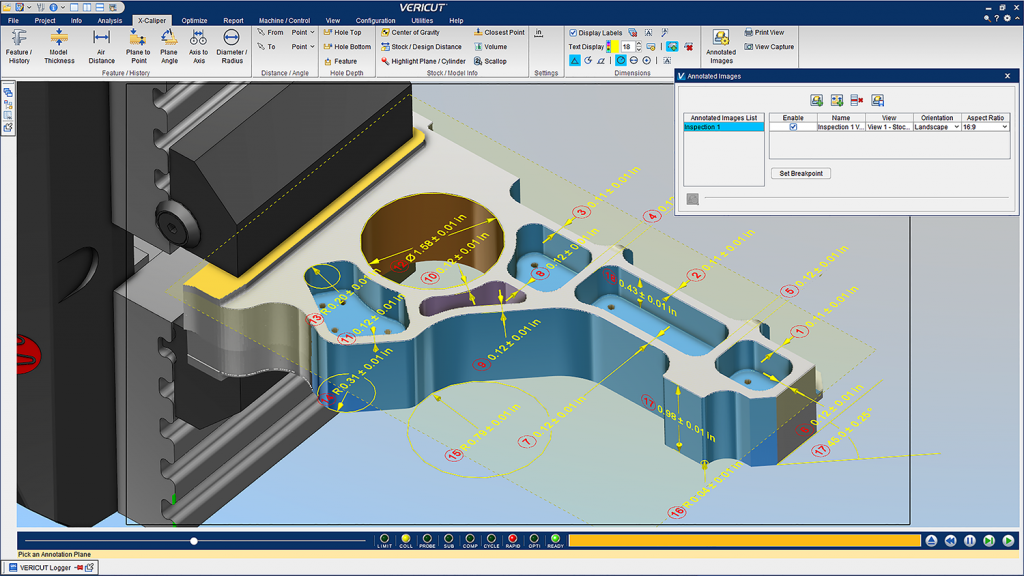
X-Caliper Annotated Images
Setup Plan has been renamed to Annotated Images. Vericut Inspection is also now included with Annotated Images.
Both Setup Plan and Inspection functionality is greatly enhanced with dimensions, notes and tolerances for checking parts at various stages of machining.
Users can create professional looking and informative setup plans and inspection images stored with view layouts – ready to print as “shop aid” documents, or to appear in Vericut’s Reports.
Shanks in Cutting Tool Assemblies
Defining shanks as separate objects from the holder and cutter enables programmers to see where these non-cutting portions of the cutter are – relative to the stock workpiece, and allows more discrete control over near miss and collision detection properties and tolerances.
Tool holder models can also be used as Shanks.
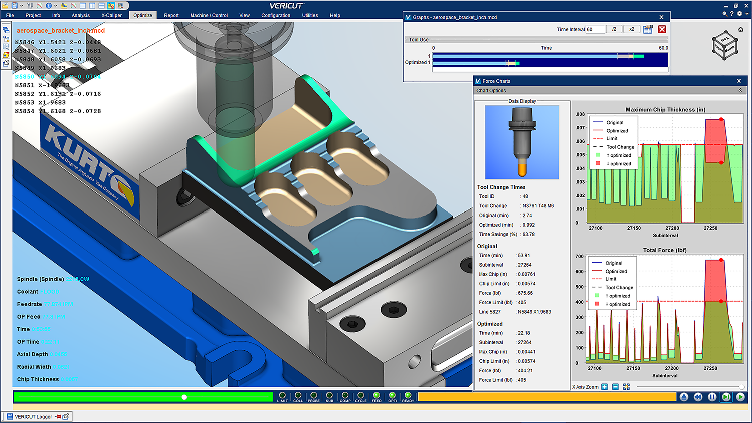
Force Charts
New ‘Save All As’ optimisation settings option added to the right mouse menu when clicking on a Force Chart.
New ability to ‘Learn From Results’ enables optimisation settings for a tool or all tools that were analysed.
Additive Manufacturing
Vericut 9.1 has a new “Additive” Default Machining Type. This enables Vericut to predict system resources that will be needed to additively build the as-designed part, including a starting stock build plate or model.
Vericut is able to build multiple parts created by a ‘nested’ build NC program, enabling additively built parts to be independently relocated or assembled for finish machining, or exported.
This feature is especially helpful for Big Area Additive Manufacturing (BAAM) and Large Scale Additive Manufacturing (LSAM) parts.
DXF Import
The DXF Import feature has been enhanced with several new features. The DXF reader can now read the layers within a DXF file and automatically detect CUT/NOCUT layers.
Additional layers can be checked on to use as additional components.


