You’ll no doubt have read about the launch of Synchronous Technology from Siemens PLM software. What really matters is how it’s implemented within the company’s products and more specifically how it affects users of Solid Edge. To get to the heart of Synchronous Technology and how it works with Solid Edge we need to look at how Solid Edge has traditionally worked. It’s a feature and history-based modelling system meaning each modelling operation is stored within a history tree. When edits are made, the system needs to recalculate each in turn one after the other, to arrive at the final form. Within that, the system also includes parametric design tools, allowing dimensions, constraints and other driven parameters to control the form of entities within each feature and to cross-link between them. Parameters range from dimension and geometric constraints within a feature sketch, to parameters that define feature extents (such as extrude height, cut depth, or the degrees used in a revolve). You can set-up parameters or constraints that link between features and geometry references using, for example, the “extrude to” option, or offset. Then you can also build parameters that are intelligently driven, referencing other dimensions or measurements.
These are the core components of any Solid Edge model – Features, History, Parameters and Constraints. To confuse things further, you also have a few Direct Editing tools. These allow you to make localised modifications to faces (such as move face) without having to edit the base feature that created that face. These are appended to the end of the history tree and should also be considered to be features (with history). So how does Synchronous Technology change this state of affairs?
Siemens PLM has taken the base technology (namely, Parasolid and D-cubed) within Solid Edge and created a layer on top of the core technologies to extend them. This is the essence of Synchronous Technology and it allows you to work in a much more efficient manner than has traditionally been the case with Solid Edge. But how does it do this exactly?
Synchronous Technology is a feature-based, but history free modelling technology. In other words, it allows you to work with features, enhances the current tools by freeing you from the need to recalculate the history after each edit and adds intelligence to your working process. Let’s dig a little deeper and look at two specific cases – when modelling from scratch and, perhaps more critically to existing users, how you use Synchronous Technology with your existing data.
Modelling from scratch
Synchronous Technology or ST (as we’ll refer to it) allows you to create parts in a very freeform manner. You create a 2D sketch, and then use a set of commands to create the 3D geometry. At present ST is enabled in a select set of operations but the selection of Extrude, Revolve, Hole, Round, Draft, Pattern and Thin Wall (or Shell) is a little deceptive. You need to consider that each enables both the cutting and addition of material in a single feature, and the manner in which you interact and manipulate geometry means that you have much more potential in terms of forms that can be created.
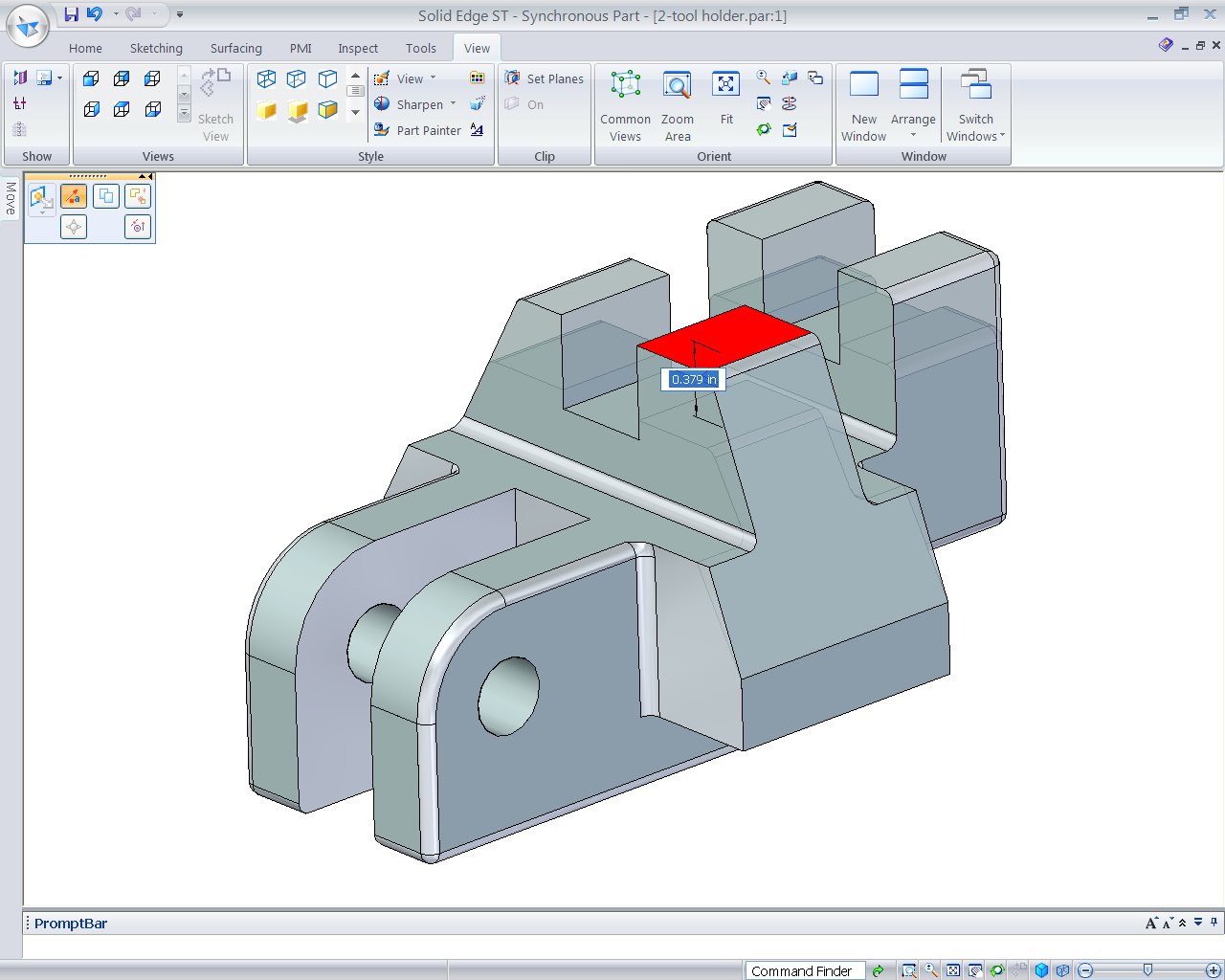
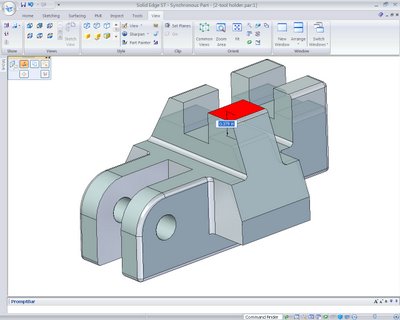
This shows a face being pulled up and a value dialled in, but what’s interesting to note is that the system also takes with it faces that are planar to that selected face (these, of course, can be overridden, so the system doesn’t get too carried away). Also worth noting is that the system maintains the fillet/blend plus the draft angle that’s applied to the outside of the part.
So, you create sketch and the direction in which you drag the arrow defines whether material is added or removed. What enables the freedom is the fact that you are presented with a great deal of feedback about what you’re doing. If you grab a face and move it, you can do it by eye or dial in a specific value, same for rotation. References are created on the fly and the UI widget is useful for moving and rotating geometry in 3D space. Also, when you drag and drop faces, the system works with a set of selection assistants that add intelligence to the process. These are called Live Rules and infer relationships such as tangency, parallelism, concentricity, perpendicularity, symmetry (around a define plane), and radii, between the geometry you select and that around it.
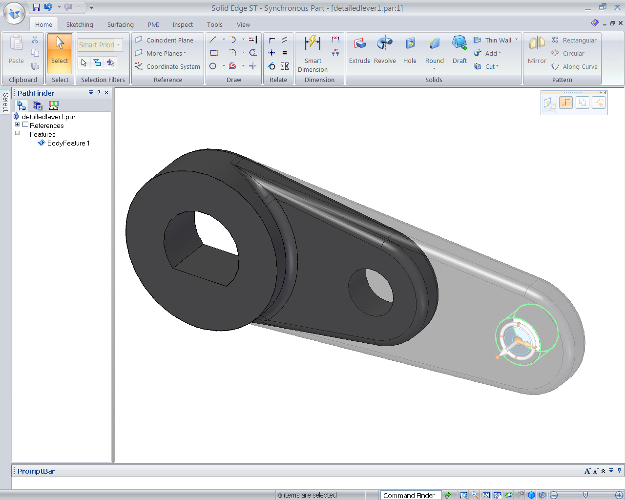
How the system works with concentricity and tangency. The user selects the hole, uses the onscreen widget to move it precisely, but because you also have a concentric condition, the whole bracket stretches. The outer edge maintains its concentricity and the tangency of the swing arm is maintained. Of course, if you just wanted to just move the hole, you toggle off concentricity and just drag and drop it.
But while it’s interesting to play with geometry to get a model into shape, within the design world you always need to be able to tie up specific dimensions and controlling factors – and this is what makes Synchronous Technology unique, for the time being at least. At any point, you can add dimensions or constraints, which can have specific values. These can be between faces, edges and other geometric features, they can be driven or driving, be linked using parametric equations and can reference each other. The point is that you apply them only when they’re needed and they are then maintained. The result is that your interaction with the geometry will respect those constraints and dimensions are maintained and again, all without having to resolve a history tree with each edit. Figure 3 shows a dimension between the centre of a boss and the end of a fixture. As you drag those features, the dimension is maintained, because you’ve defined it. You work with assemblies in a very similar manner, in that you grab, drag and drop, move and rotate faces in multiple parts and the system will calculate the updates automatically. In addition, references can be made between separate parts, cross-referencing faces where required.
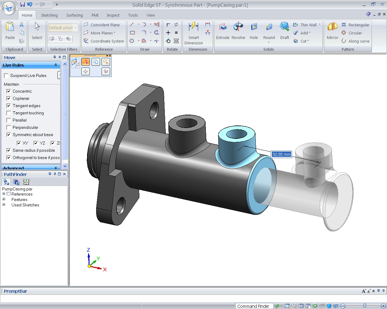
This shows how the system works with multiple selections. By selecting the boss and the end face, you can stretch the part as you need to, rather than having to dive in and edit several features right back to the original extrude that created the pipe. What’s absolutely key to note is that at no point are you editing features in a history – you make your edits and the system updates pretty much in real time.
Working with existing data
Synchronous Technology looks dammed interesting as a modelling technology, but the big question is how does it affect your existing data? Some organisations have been using Solid Edge for over ten years and built up a huge amount of live data, but how can they adopt this new way of working and still maintain that data? The answer is simple: leave it as it is. Solid Edge is now architected to work into two modes. Solid Edge, as standard, with the full range of features and functions that have made it one of the most impressive applications on the market, and then with Synchronous Technology enabled. But you need to be aware of a couple of things.
Firstly, when you open a new part, you have two options. You can either open the part to be built with the traditional feature and history based modelling tools. Or you can use an ST enabled template, which switches on these new tools. More importantly though, what happens if you take an existing part built with a rich history of features that control its design and move it into the Synchronous Technology mode. The answer is thus:
When you open a history-based traditional model as a synchronous part, the system prunes out the history, but retains the information required to maintain the features in a Feature Collection. Siemens is referring to these features as Procedural Features and covering things like chamfers, blends, patterns, and shells. This means you can edit them and the system will maintain the design intent you stored within them. For example, even though a pattern is typically a history-based feature, you can still edit the number of instances within an array or edit the dimensions of a hole using standard hole definition terminology (such as counter sink or counter bore).

This shows a Solid Edge ST part. Dimensions have been placed after the design work has been done, in order to formalise the design intent and lock down dimensions. What’s key is that you can also create the same parametric relationships between dimensions to drive design change as you would within a history and parametric modelling system.
It’s important to note that you can’t really take a part back into the traditional modelling environment once you’ve included ST-based work. If you do, then the system treats it as a bumb solid (and its also worth noting that you can you can put ST parts in a traditional assembly and they will update as need be. These things are key to working out an adoption strategy. Synchronous Technology is brand new. Yes, many of the components have been around for some time, but this is the first time that you’ve been able to combine the flexibility of explicit modelling tools such as CoCreate with the parametric- and feature-based tools within Solid Edge and many others. The fact that the system can solve and handle design change with such ease means many things, but the bottom line is this. If you can affect design change within a part or assembly without having to firstly work out the complex history that gets you to the end result and not have to wait to make those changes, then you’re looking at a radically more efficient product development process.
In conclusion
Synchronous Technology has set tongues wagging across the 3D design world. If you ‘Google’ the term you’ll find endless amount of blogging about it to varying degrees of accuracy and many have tried to pull it apart. What’s been missed to date is that this technology is at a formative stage in development. Yes, you can do a hell of a lot, but you don’t get all those other tools that have been a core part of Solid Edge for the last decade and more within the synchronous technology mode.
This is vitally important; within Solid Edge, you now have two choices: To go synchronous or not. When you do this is down to your projects and even on a part-by-part basis. The benefit you have is that if the ST enabled tools can’t create what you need, you have the last decade’s worth of Solid Edge technology available to do things the traditional way. If you can adopt it and reap the benefits as it makes light work of modelling. But make sure you are aware of the limitations and the impact of moving existing data. The good news is that this technology has huge potential and even at this early stage, it’s clear that Siemens has something unique on its hands.