Perhaps the most eagerly awaited bit of technology in the last few months has been Inventor Fusion. This is Autodesk’s first foray into the world of direct editing of 3D geometry, which has been one of the most talked about technologies of the past 12 months with products like Solid Edge with Synchronous Technology, SpaceClaim and CoCreate creating much of the buzz. Yesterday saw the application launch, so we thought we’d give you a guide to the functionality you’ll find on the web-site.
Unlike Inventor 2010, Inventor Fusion doesn’t rely on history. Features are still very much an intrinsic part of the application, but it doesn’t carry with it the headache of history recalculation when features are edited.
Autodesk first showed off Inventor Fusion at its annual user event, Autodesk University, in December 2008 and we got the scoop on DEVELOP3D.com with some rather shaky videos. Seven months on and the technology has just been made available for download from the Autodesk Labs web-site. Out of all the CAD vendors, Autodesk has one of the most impressive Labs sites and many technologies that started out in Autodesk Labs have been refined over the past couple of years and now form a key part of Inventor and its associated extensions, such as simulation and tooling. Inventor Fusion is likely to remain in Autodesk Labs for some time as each successive public release is put out for all to see, play with and give feedback to help drive its development.
I’ve been lucky enough to have access to the software for the past couple of weeks prior to it going live on the Labs site and have spent some time playing with the application. Over the next few days I’m going to share my experiences and conclusions of Inventor Fusion, kicking off with the minimal User Interface (UI).
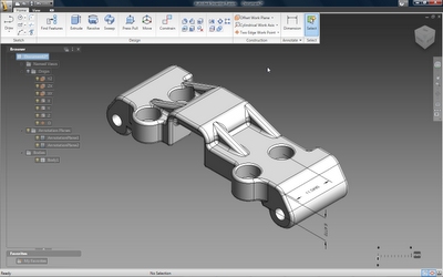
The Inventor Fusion UI. Dynamic. Very.
User Interface
The Inventor Fusion UI is minimal to say the least and because it has a small set of commands (which actually do a lot more than might immediately be obvious) there are just two panels and tabs. Let’s look at the basics of view manipulation first.
The View tab and panel gives access to the view controls for view and display. Like Inventor 2010, there’s a View Cube at the top right of the UI, then the display toolbar below gives access to the rest of the view controls.
In terms of navigation, all of the controls for pan (middle mouse button or F2), zoom (scroll wheel or F3) and rotate (F4) are there, with the exception of the shift + middle mouse button combo for rotate (a little tip for Inventor 2010 users courtesy of Steve Bedder). There’s also control over the display of grids, shadows, View Cube, navigation bar, and browser. As in Inventor 2010, it is worth noting that there is a toggle for orthographic or perspective display, but I encountered some display issues when in perspective mode, so be warned (I’m told this is to be fixed very shortly indeed).
There is also a material definition and texturing control for parts, so the visual appearance can be set to help put models in context. The familiar browser – now integrated into the user interface, rather than as a separate panel – gives access to named views, origins, work geometry, annotation planes and a feature list (Note: no history).
The final command for this panel is the ShowMotion tool. This is new for Inventor-related products and it sees cross-pollination of technology from Autodesk’s Showcase product. Showcase excels at helping users quickly create presentations to show off product models, and allows view positions and display states to be captured and animated – think a 3D PowerPoint for design review and presentation.
ShowMotion enables users to create a shot for a view and add the animation details so it can be stored for reuse and presentations. Simply bring up the little panel in the UI, flick between views, and run simple animations. It’s very slick.
Modelling from scratch
There are several things you need to familiarise yourself with before digging into Fusion. Firstly, the user experience is much more dynamic than Inventor (and many other applications, for that matter) and there is much less reliance on toolbars and icons. While all of the modelling and editing operations are available on the Home toolbar, once you get the hang of things, you’ll find you don’t use this much. This is a heads up interface to the extreme.
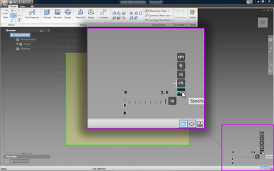
Fusion Tip #1: Fusion defaults to Inches. If you want to switch units, look at the dimension indicator at the bottom right corner of the screen. Click Inches and select from a number of unit displays (mm, cm, ft, metres are supported). The rule to the left gives you control over snap distances for the Press/Pull, dynamic manipulation controls. You’ll also see the toggle icons for grid, snapping and ground shadows at the very bottom of the UI
.
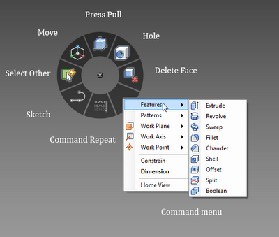
Much of Fusion is driven from marking menus, something that was introduced into the Alias products many years ago and which has been adopted by many modelling packages as a replacement for the context sensitive right hand mouse button menu. Fusion combines the two. To begin, hover your cursor in the middle of screen. Now, hit the RMB (Right mouse button). You’ll see a radial marking menu pop up and a more traditional menu. The radial commands give you access to the following:
The Marking Menu’s give you access to the most commonly used command around the cursor and a secondary, more comprehensive list of commands in the more traditional menu.
For modelling. To begin, select Draw. This brings up the usual plane selection triad and you can either select a working plane or one from the browser. Once that’s done, the view presents the plane normal to the screen, starts a sketch and switches on the grid if you’ve turned it on (either from the View Panel or from the small icon at the bottom right of the screen).
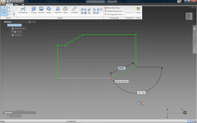
Inventor Fusion’s sketching tools dynamically add ad-hoc dimensions that allow you to eye-in values (the grid helps greatly) or to tap in values to lock length and angle.
Immediately the line, circle, arc drawing tool starts and you can create a sketch. Sketching within Fusion is pretty slick. Hit the start point, add the first line and immediately the dimensions are displayed, for length and angle. While you can eye these in, it’s much more powerful when tapping in known values. The tab key switches between the length and angle, and you can tap in one and eye in the other – or indeed, tap in both.
To create an arc, you drag from the end point of your last line and add the arc, again eyeing in or tapping values as you go. This process can be used to create a lot of geometry, but for more complex forms there is a pretty comprehensive range of additional sketching tools, including splines, circles, rectangles, filleting, other methods of arc construction and extending and trimming. These are available either from the Home Panel or the marking menus. To assist with geometry creation there is also the usual range of work-plane, axis and point tools to create references. These are simple to set-up and use the same dynamic movement and positioning tools as every other command.
Automatic closed loop profile detection gives you the ability to create geometry very quickly. Model glyphs give you access to operation options, such as direction of pull, and draft angle.
Once you have a closed profile (Note: Fusion only supports closed profiles at the moment for feature creation, as there’s no surfacing), you’ll find that the profile automatically becomes shaded indicating that it’s ready for feature construction. To exit the sketch, you can either hit the small icon at the bottom right of the sketch plane or hit the marking menu and choose the modelling operation. Now, this is where things get interesting so let’s look at the various commands available in this first Labs release.
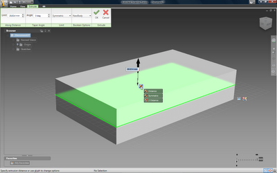
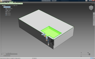
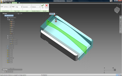
The major modelling operation is the Press/Pull command, found in the marking menu or the panels. This can be used to create extrusions, either to add material or cut it away. Hit the command, select the profile you want to work with and the display brings up a preview and a small arrow. This lets the geometry to be dragged out to the desired depth (again, you can key in or eye in values). There are two additional controls you need to be aware of. Firstly, with the small glyph near the feature (by default it shows a plane and an arrow), you can either define the extrusion as running from one side of the sketch-plane, from both (to different values) or symmetrically about that plane. Secondly, below the length arrow, you’ll see a small ball. Dragging this will create the required draft angle. Of course, you can also tap the values into the panel that pops up at the top of the screen.
Adding addition sketches allows you to quickly sketch, pull/push new features into your model.
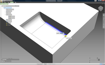
The Press/Pull command is a multi-purpose tool, in that it allows you to create extrudes and fillets depending on your selection. Select a profile and you have a cut/add extrusion. Select an edge or set of edges and you have filleting to hand. Filleting allows you to work with single edges and multiple selections and you simply press the fillet into place. There is also a handy “match radius” glyph that allows a numerical reference to be taken from another existing fillet radius.
The Press/Pull command can create extrusions, offsets and fillets depending on your selection.
Move
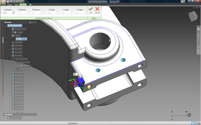
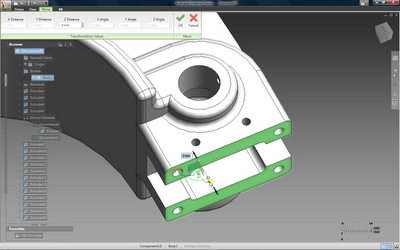
While the Press/Pull command will be used in most instances when modifying and adding geometry, the Move command lets you work with existing geometry and shift it – simply grab the geometry and use a triad to move or rotate sets of faces. There’s also a very handy ‘Select Other’ tool from the marking menu. This gives a heads up way to find geometry related to your current selection, either by topological neighbour (edges or faces which are connected directly to your current selection), by Z depth (which allows you to select obscured or hidden faces behind your current selection), or using the feature selection tool (to find extrude, fillets and such from your selection). The options are displayed on-screen with dynamic previews that show exactly what you’re working with. These allow you to grab the feature or face you want to work with, and then hitting the move command brings up the familiar Triad. This gives you several things to do with your geometry selection. Each axis on the triad allows you to move the geometry in that direction. There’s also a visual reference for rotating geometry about an axis and a free move option using the sphere at the origin.
Using the Move Triad and the F5 key allows you to grab geometry, align the triad to the direction you want to move that geometry and pull it into position.
These small black arrows animate to you show you how your geometry selection can be manipulated.
More traditional features
Alongside the Press/Pull command, there are familiar commands for sweeps, revolves, fillets, chamfers and shell. There’s also a Delete Face operation, but it’s worth noting that the system will only allow you to delete a face if the removal of that face results in a watertight model, once the boundaries have been filled in.
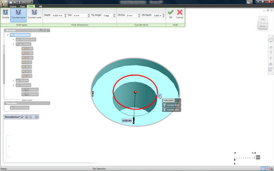
The hole command epitomises Inventor Fusion’s dynamic way of working. When you create a hole, you have a number of options for a straight bore, counter bore or counter sunk holes. These are not standards-based yet (I’d expect that’s coming at some point, as Autodesk already has a wealth of data for that within Inventor 2010), but you simply drag and drop the handles into place to create the feature. That feature is then stored in the browser and can be copied/pasted into another position when required.
Hole creation isn’t yet standard-based, but uses the same dynamic interaction methods to define the various constituent parts of simple bores, counter sunk and counter bored holes.
Alongside standard features, there are patterning tools (radial and linear), mirror of features and part splitting. Because these are maintained as features and remain intelligent, modifications to one mirrored face will result in updates to others within that Mirror set.
Reference geometry is available to assist creating reference with accurate references.
While this might sound complex, in reality, it’s a very easy way to work. When you build successive features, you follow the same, sketch, model, preview, build workflow. Sketching is much more fluid than in Inventor 2010. If you create a sketch on an existing face, the system uses the boundaries that already exist and you can simply drag that profile loop into shape, without all that messy face splitting business.
That’s it for Part One. We’ll be back at you soon with Part II looking at working with existing geometry, assembly creation and model annotation. Before we go, no post would be complete with some video.

