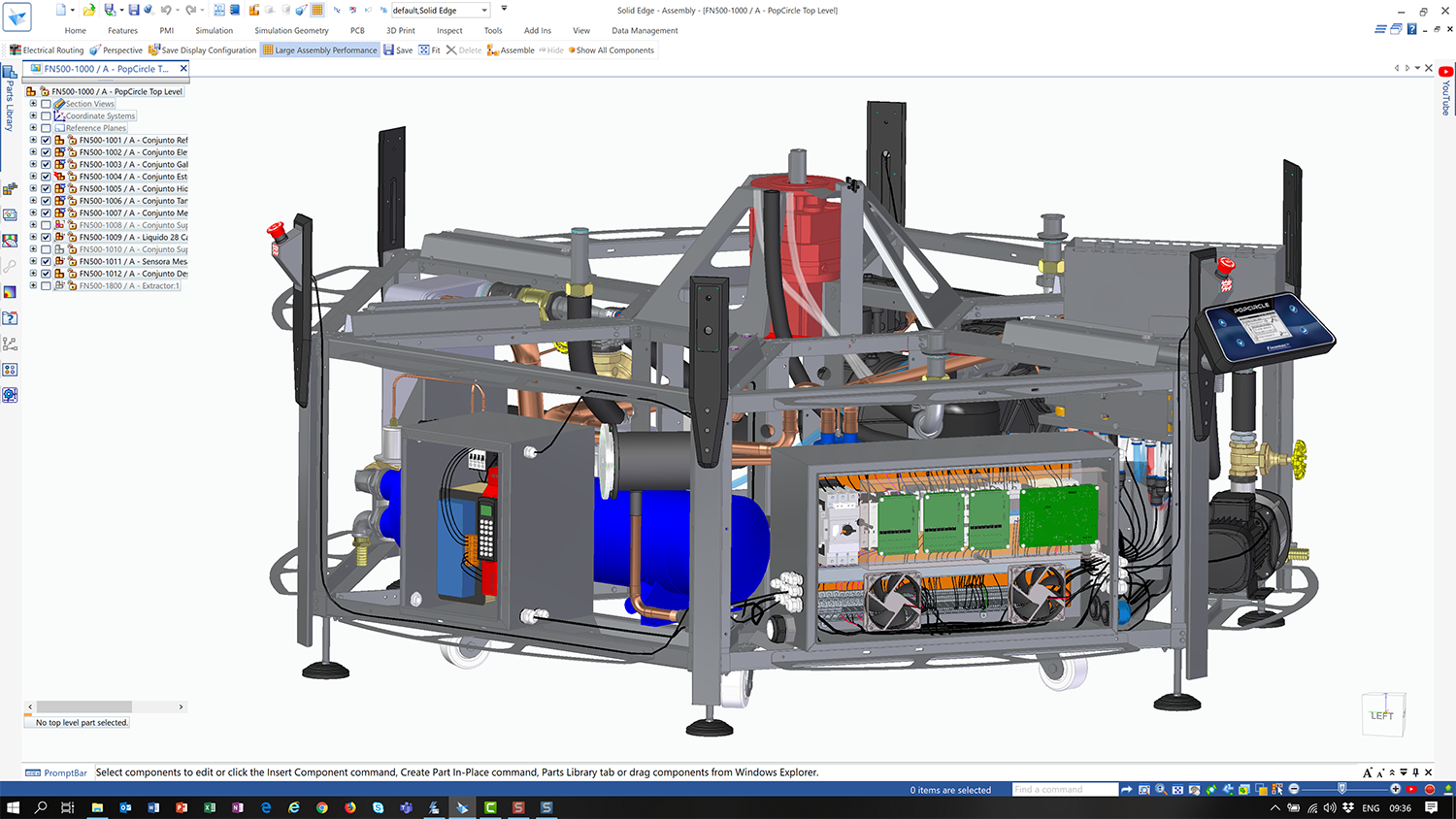
Solid Edge 2021 neatly combines improvements to existing tools with the introduction of new technologies from elsewhere in Siemens’ growing software portfolio, as Al Dean reports
For most DEVELOP3D readers, Solid Edge requires little introduction. After all, it’s a design tool targeted at the mainstream, developed by a giant in this market (Siemens Digital Industries Software), and has been on the market for the last two and a half decades.
As you’d expect, it runs the full gamut, from standard parts, assemblies and drawing creation to simulation, machining, rendering and data management.
Over the course of the last quarter-century, Solid Edge has acquired some interesting technologies. These have included tools for surfacing, referred to as BlueSurf and dating back to the early 2000s; its synchronous technology, which mixes direct modelling with intelligent feature and relationship management; and the more recent introduction of convergent modelling, which sees a more cohesive set of tools for working with solids, surfaces and polygons, all mixed together.
Alongside these geometry-focused updates, Solid Edge 2021 has also benefited from an expansion in add-ons, based on technologies acquired by Siemens.
These include the introduction of FloEFD for fluid flow and thermal simulation; better PCB import; and electrical design capabilities using technologies from Mentor. So shall we explore what the 2021 release has to offer?
Core modelling & UX updates to Solid Edge 2021
Let’s kick things off with a look at enhancements and updates made to the core tools within Solid Edge. As ever, a good place to start is the user interface. While the Solid Edge interface hasn’t changed to any huge extent for the 2021 release, one new tool in particular will make using it a little more efficient – namely, the adaptive Command Prediction tool.
This tool analyses the commands you use most frequently and then automatically presents them to you – in the first instance, in a ribbon bar found at the top of the modelling window. In other words, the system uses machine learning to ‘understand’ how you tend to work, depending on the task and based on your previous operations.
If this sounds familiar, that’s because it’s the same technology that Siemens introduced to its NX system last year.
As with the NX implementation, there are some interesting capabilities running alongside this. It’s possible to take the data gleaned from the actions of an experienced user and reuse it to get new users on your team up to speed with the way things are done, pointing them to the most commonly used commands within your organisation.
It’s worth noting here, however, that there are no aggregation tools, so you need to pick one specific user whose data you want to reuse. This approach, of course, runs the risk of reinforcing bad practices, too, so my advice would be to pick well and use this capability cautiously.
Alongside this, there have also been a number of updates to how Solid Edge’s core modelling tools work. Since these will be applicable to most users, irrespective of industry, let’s walk through them.
One of the big changes is how the system handles large assembly data during import. With systems like Solid Edge, the typical data import process has been to take a STEP or IGES file, parse it and create separate part and assembly files on disk that reconstruct that geometry.
By contrast, the system now keeps part and sub-assembly data as part of the original assembly file, without creating any additional data files on disk. This means they should load more quickly, since the system isn’t spending time pulling together all of the external references and displaying them on screen.
Elsewhere in the core updates, there have been a few tweaks to how the system handles operations on ‘inactive’ parts and subassemblies. Like many systems, Solid Edge allows you to display just the graphic representation of parts and assemblies, mostly to make working with complex and large scale assemblies more efficient.
For Solid Edge 2021, it’s now possible to carry out more operations on those graphics only, such as creating assembly relationships (mates, aligns and so on), taking measurements, and making synchronous edits at the assembly level.
Also on the assembly front, it’s now possible to copy and paste multiple parts and sub-assemblies from one assembly to another. Here, all internal relationships to the copied parts come along for the ride. Solid Edge 2012 also walks the user through creating the relationships needed to position all the new parts.
The last generally applicable update I’m going to cover before getting into other areas of Solid Edge 2021 is a small one, but important for those who use their product models to replicate how a physical product will appear.
In short, it’s now possible to add decals to your models. This works exactly as you might expect, allowing you to add product information, proof labels and warnings and such, before they get anywhere near a vinyl cutter.
Fabrication, frames & sheet metal
Sheet metal functions have been a strong selling point for Solid Edge for many years now. The system has attracted a healthy share of its users who, if not solely focused on sheet metal fabrication, are certainly engaged heavily in design and fab as part of their wider manufacturing processes.
The existing tools in Solid Edge are already mature, but that doesn’t mean that there’s no room for innovation or, indeed, catching up with what other vendors are doing.
One such enhancement for this release focuses on multi-edge flanges, making it possible to create multiple flanges from an edge selection in one step. At first glance, this looks like a common feature in most 3D design systems these days, but what’s really interesting here is that these flanges are intelligent.
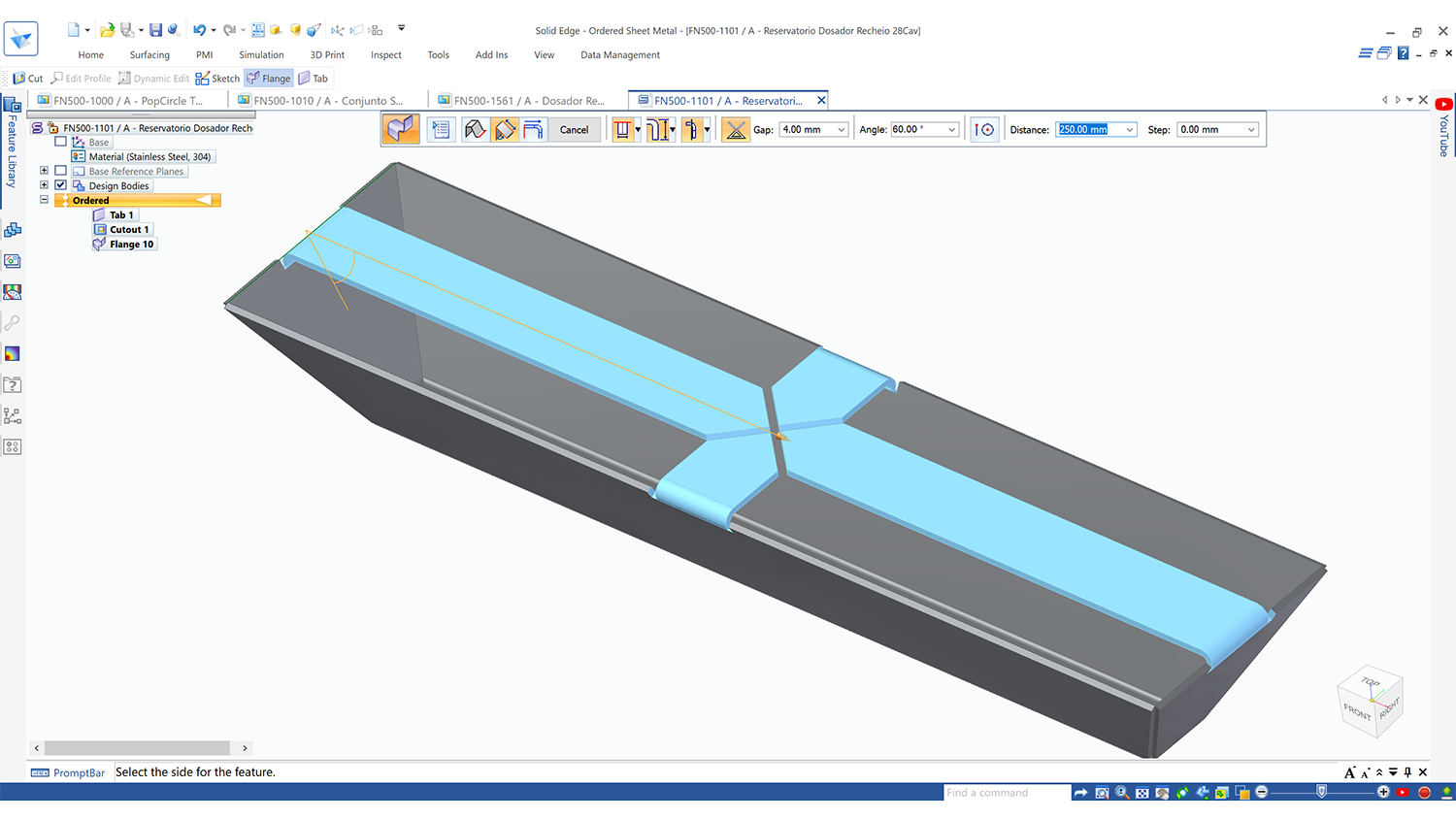
Trimming is performed automatically where they meet and you can also include an offset gap between forms, for both fabrication/assembly and welding.
While Solid Edge has had the tools to design and engineer sheet metal forms for decades now, a more recent addition is the ability to carry out nesting of sheet metal forms.
While this isn’t the fully fledged specialist application set needed by those deeply embedded in fabrication, it does provide a set of tools to carry out quick nesting operations, identify the optimum use of sheets and gain a better understanding of both material and cost – whether that’s for production or just estimation/quotation.
On that point, an update to this toolset for this release that will help with estimation/quotation is the ability to open an assembly file and have the nesting tools find all applicable forms. By allowing you to add in your material requirements, the system performs the layout across multiple sheets for you, taking into account multiples, if found.
On the frame design side of things, the current tools are well-developed and mature, but as ever, a few tweaks here and there can make life easier for those who use them regularly.
For the 2021 release, the ability to automatically add weld gaps between frame members can be turned on – something that’s increasingly important if you’re using laser or plasma cut tubing. You can also add in end caps to your frame members quickly, either using a standard size or basing them off the frame section with a number of controls.
Subdivision Surface Modelling
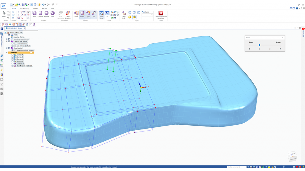
Now let’s move on to some new technology for Solid Edge: subdivision surface modelling. If you’ve been watching the wider 3D design technology industry, you’ll be aware that almost every vendor has integrated some form of sub-d modelling into its toolset.
The Solid Edge team is probably one of the last to make the move. If you’re not familiar with this technology, it provides a set of tools for defining complex organic shapes that previously would have required some pretty heavy solid and surface modelling to achieve.
Where needed, sub-d bodies can maintain curvature continuity to get the shape you want quickly. (They’re also useful for creating sharp blends between complex junctions and surface transitions.) As you might also expect, the sub-d tools in Solid Edge feature the usual array of form pushing and pulling, symmetry control, bridging, blending controls and so on.
In terms of how these modelling tools work with both ordered (history-based) and synchronous model-led parts, they follow a familiar pattern, with the sub-d form stored as a separate ‘feature’ on the feature/history tree.
Reverse engineering in Solid Edge 2021
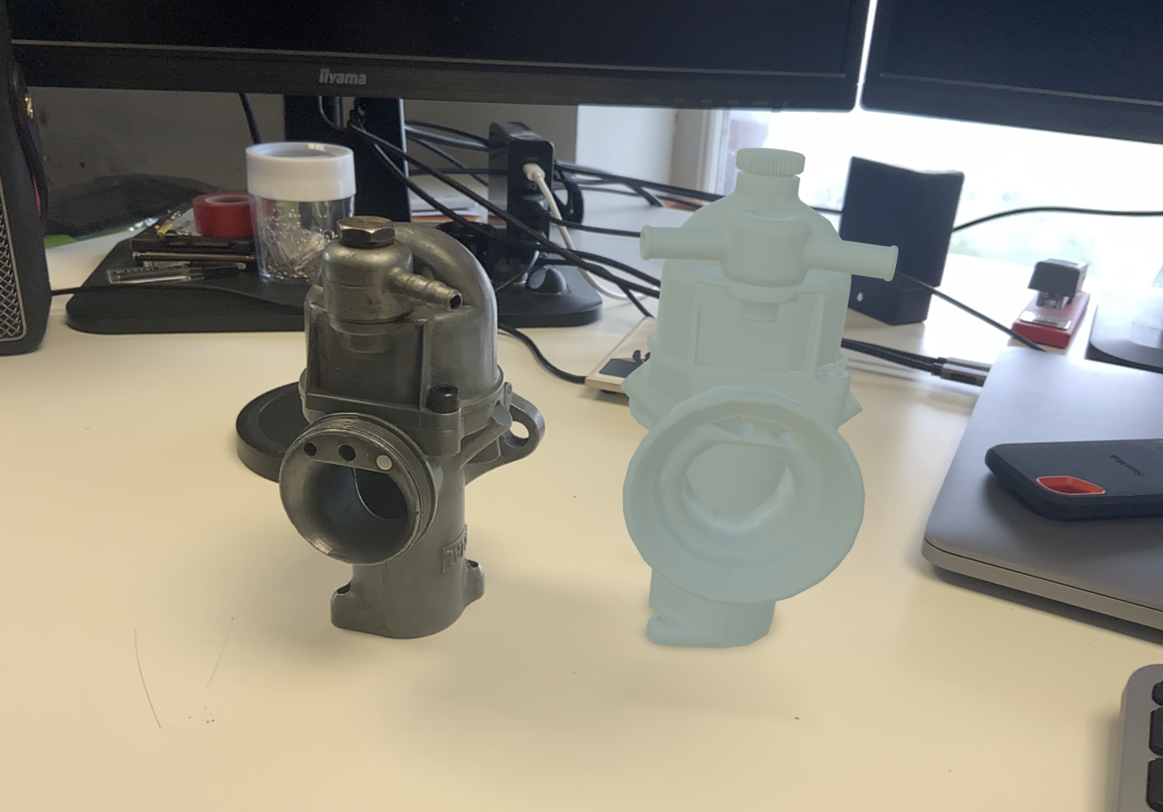
Next up, let’s look at reverse engineering tools. This has been a focus for Solid Edge for a few releases now.
Two years ago, Siemens introduced the concept of convergent modelling to Solid Edge. This allows you to work with mesh-based data alongside more traditional forms of solid and surface geometry. At the same time, the development team also started introducing tools that allow you to bring in mesh-based data from reality capture workflows (such as laser scans) and do some of the post-processing work you’d typically perform on the scanner side.
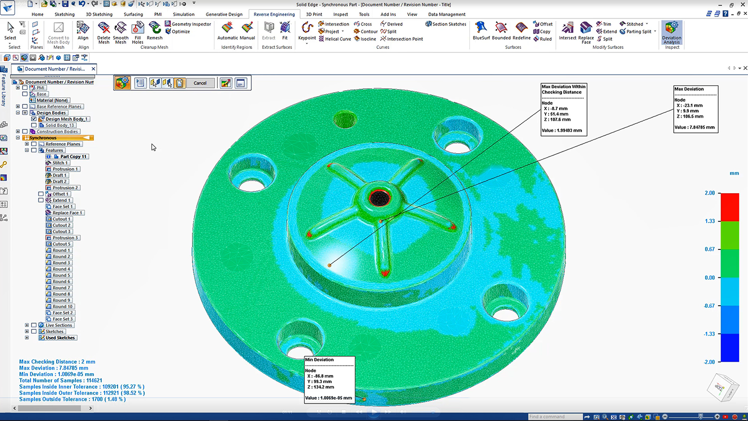
These tools range from mesh fixing and repair tools to mesh decimation, making what might otherwise be very heavy data work far more efficient. They also include surface-fitting tools to build up analytical geometry from the basis of scanned data.
For the 2021 release, new performance enhancements make the system work more quickly – up to 50 times quicker, according to Siemens executives. Deviation analysis, meanwhile, shows you any deviations between your scan and the model you’ve worked up.
Electrical design & PCB
Recent releases have seen Siemens place a great deal of focus on the integration of electrical design with Solid Edge. In 2019, for example, we saw the introduction of an add-on for wire, harness and routing, as well as PCB import and interoperability.
For the 2021 release, there’s a new addition to this stable of tools, specifically focused on the layout of control panels. Considering the prevalence of machine design in the Solid Edge community, this is going to be seriously interesting.
The workflow looks like this. You begin by preparing the wiring of the panel at a schematic level, as you would with most electrical design projects. Once that’s done, you start a new panel layout, adding in your shape, a border, a back plate and bringing in a terminal strip. You then start snapping devices to that rail and positioning your components.

What’s interesting is that Solid Edge uses your schematic representation to help you in this process, so you lay it out more intelligently. Of course, you’ll also need to route from your control panels to the components and subsystems that they control – and there’s been work done on this front too.
Solid Edge has had formal routing options for wiring for a while, but this new approach is a little less formal, allowing you to quickly route a cable or harness from your panels to components/subsystems and quickly pick points and geometric features/surfaces to snap them to along the way.
It’ll save you all of the effort of positioning those clips and other mounting components you’d typically have to organise and give you solid, sufficiently accurate data on wire lengths, which subsequently get passed back to the BOM.
On the PCB front, there hasn’t been too much action other than an update to the import options, with the addition of IDX 3 support, and support for swapping detailed models within Solid Edge when working with the Pads Professional and Xpedition, compared to the usual abstracted outline view.
Flow simulation
Alongside the core 3D design and manufacturing tools, the last few releases of Solid Edge have seen greater inclusion in the mainstream offering of technology from the wider Siemens product portfolio.
One of the highlights for those with an interest in fluid flow simulation has to be the introduction of Simcenter FloEFD (the new name for FloEFD for Solid Edge). This brings both fluid flow and thermal simulation to Solid Edge in an integrated manner for the first time. (It’s the result of Siemens acquiring CD Adapco and its Flomerics products some time ago.)
For the 2021 release, there have been a few important updates here that are worth discussing. One of these is the new Package Creator, which allows you to create components as a complete package, along with all of your manufacturing and performance specification information, which can be integrated into a flow simulation.
There has also been work done to improve the connection between thermal results from Flo-EFD and the structural simulation tools in Solid Edge. It’s now possible to export results and bring them into a structural study as a thermal load. This, of course, requires that you maintain the same set of geometry between the two simulation types (so that the system can map thermal loads to faces), so care needs to be taken with any abstraction or defeaturing.
Solid Edge 2021 & data management
To round things out, let’s look at data management. It may not be the most exciting of topics, but it’s crucial for many organisations. The Covid-related shift away from central design and engineering offices towards more remote working practices, in particular, makes this a big focus for customers right now.
While Solid Edge’s data management offerings have shifted over the years, they have always done so with the idea of offering two levels of support and capability. At a basic level, the core data management tools in Solid Edge 2021 work alongside your file structure and basic networked drives/shared folders, to support rudimentary operations like searches (whilst remaining aware of the complex interactions and links between parts, assemblies and drawings) and data protection (check-in/check-out), as well as enabling OS-level previews and such.
For the 2021 release, there are two updates. The first is that it’s now possible to use the right-click menu in the file browser to open assemblies in a number of ways – either as standard, as a reduced size assembly, or as a specific configuration.
There’s also a new add-on for this release that enables search by shape. What’s that, you might ask? The answer is pretty simple. Instead of using only textural, metadata-based strings or classifications to search for parts, you can use geometry to search for similarly shaped parts. This new Shape Search Server add-on for Solid Edge Data Management allows you to use the sketch of a part in Solid Edge to search against all of the data within your file system that it has already indexed.
If you’re looking to get more serious about data management, Siemens also introduced a Solid Edge-focused implementation of its Teamcenter PLM system some time ago. This is intended to be useful on an out-of-the-box basis, but as always with PLM systems, the more you do with them, the more you need to configure them to suit your requirements. Teamcenter is a complex beast, but the Solid Edge team has built a set of presets and templates designed to get smaller organisations up and running more quickly.
For the latest release, Teamcenter for Solid Edge 2021 brings a bunch of updates and enhancements, so we’ll just outline the most useful ones.
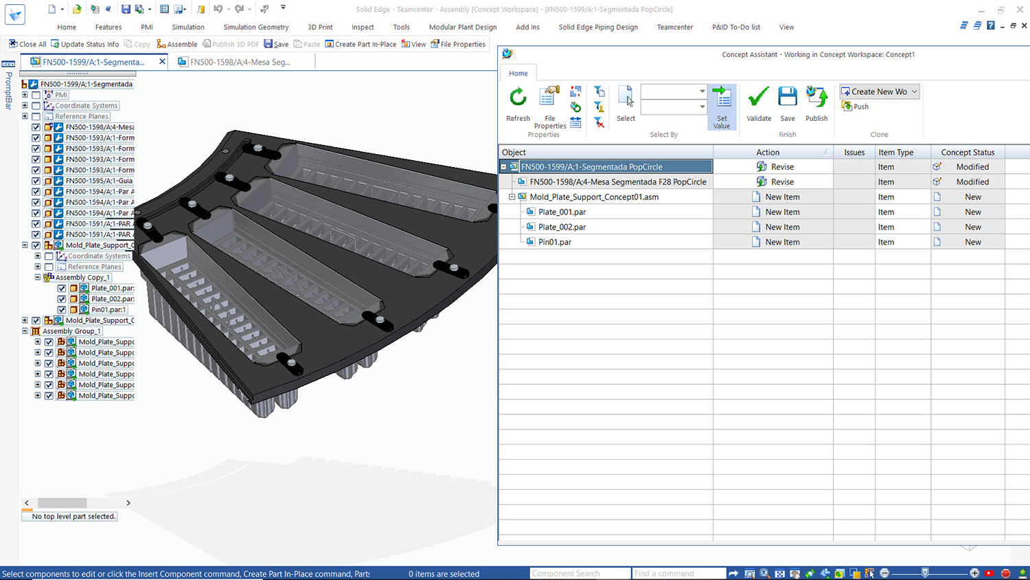
The Teamcenter Concept Workspace tools, for example, are interesting. We’re all accustomed to the idea that data management systems allow you to manage design, engineering and production data in a controlled and centralised manner. But it’s often the case that it would be useful to carry out the earliest stages of a project outside of a managed environment, because it’s here that thinking, experimentation and iteration are quickest and fundamental to success.
This is the purpose of the Teamcenter Concept Workspace, which allows you to take data from Teamcenter (for example, that which relates to a product you’re looking to refresh) and place it in a sandbox.
In that way, you can work on it without messing up your carefully managed revisions and intelligence. This also provides you with tools to compare your experiments with data held inside Teamcenter, then transition them into a managed environment when appropriate.
In conclusion
Solid Edge has certainly grown in the last few releases. In particular, it now benefits to a far greater extent from technologies derived from elsewhere in Siemens’s expanding product portfolio. While other vendors have expanded their toolsets through partnerships with third-party vendors, Siemens has the benefit of already owning those tools in-house.
While the tools added to Solid Edge typically focus on expanding its reach within a customer organisation (to include electrical design specialists, for example, rather than just the mechanical engineers), it’s also good to see that there’s been work done to expand the tools for core users too.
Subdivision surface modelling is something that a lot of users are interested in. But while it’s often pitched as a way to quickly create complex models, the reality is a little less ‘magic bullet’. You still need to have a good idea of what you’re doing and plan your workflow carefully, otherwise you’ll end up in a horrendous mess. That said, those with a need for complex forms will find it an awesome tool to have in their armoury.
The expansion of the reverse engineering toolset, along with a performance boost for polygon mesh data, means that this type of work can be conducted in your workhorse design system, rather than relying on third-party applications – something that’s always a benefit for efficiency, over and above the associated cost reductions.
All in all, Solid Edge 2021 is a pretty solid release, which neatly combines the expansion of existing tools to do more and to work more efficiently with bringing new technology to the product range.
After all, when you’re looking at a system like Solid Edge, a mature toolset is an incredible benefit. But finding new, more efficient ways to work is just as important – and arguably, more so.
Solid Edge 2021 offers a good mix of both.
Teamcenter Share: Bringing Data Collaboration & AR to All
One of the most interesting additions to the Solid Edge 2021 release is the Teamcenter Share service.
This is not a Solid Edge-specific enhancement per se, since it’s just as applicable to NX users or indeed, users of any other CAD system. But it’s certainly worth taking a look at in the context of this review, as it’s strikingly similar to the Solid Edge Portal service that Siemens launched a few years ago.
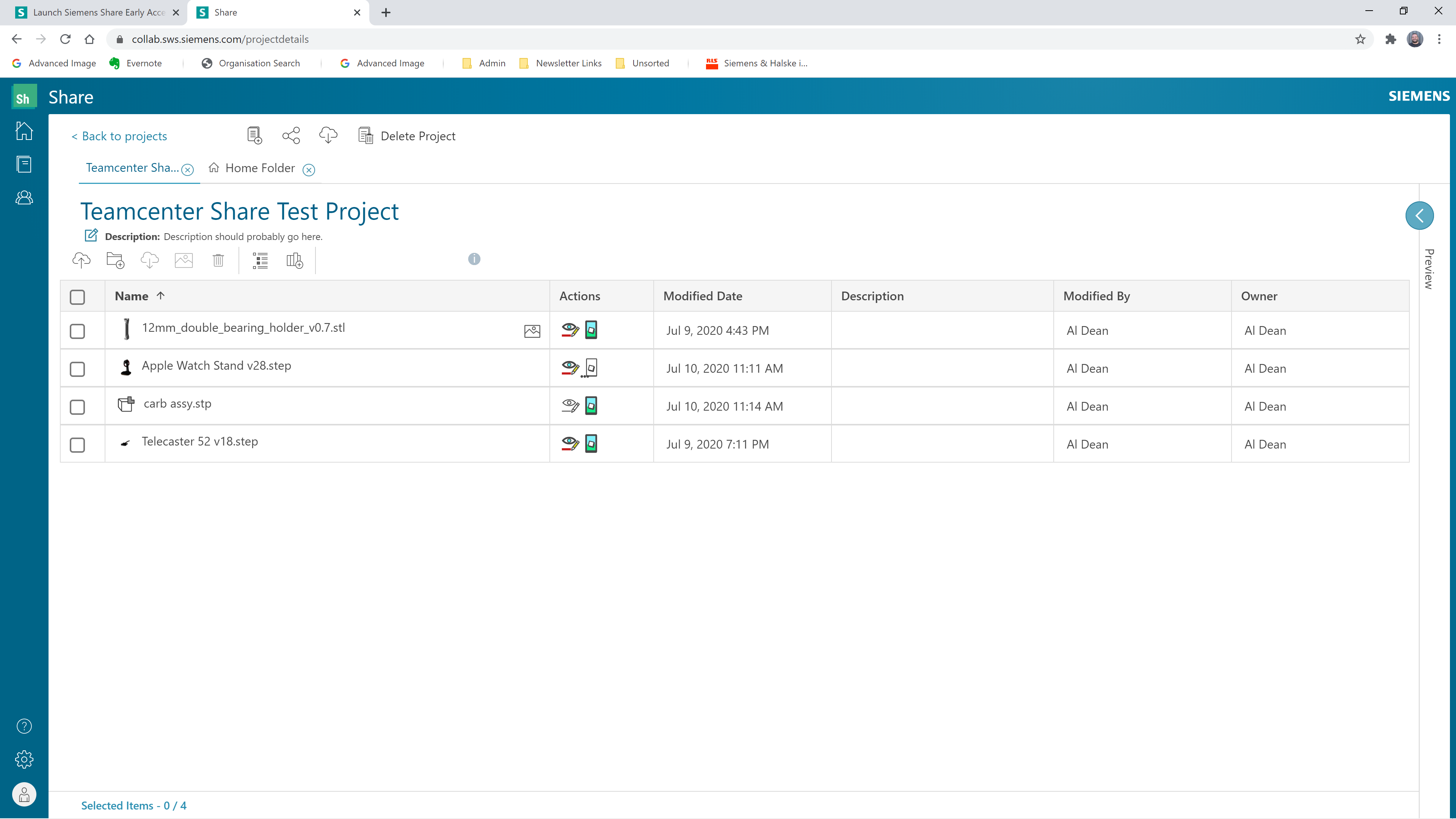
Essentially, it’s a cloud-based view, mark-up and collaboration service that centres on 3D CAD data.
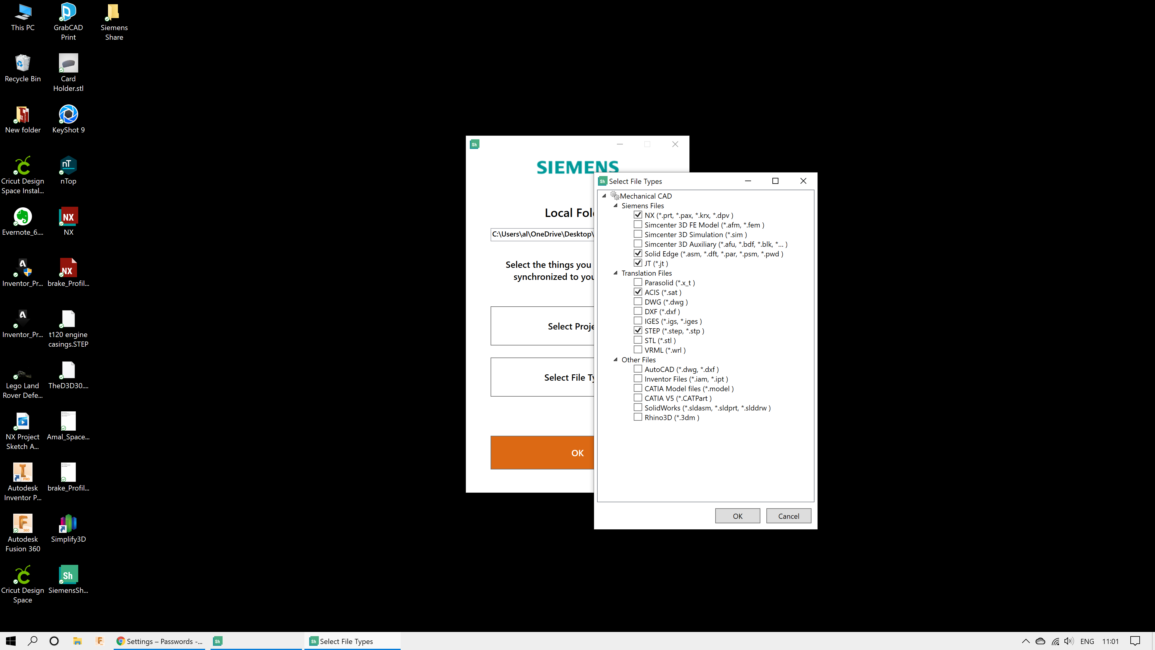
You sign up for it, get a certain quantity of storage space, and you’re able to upload your CAD geometry. For this, you either use the browser or the new desktop synchronisation tool, which monitors a specified folder on your desktop for file types to send to the cloud.
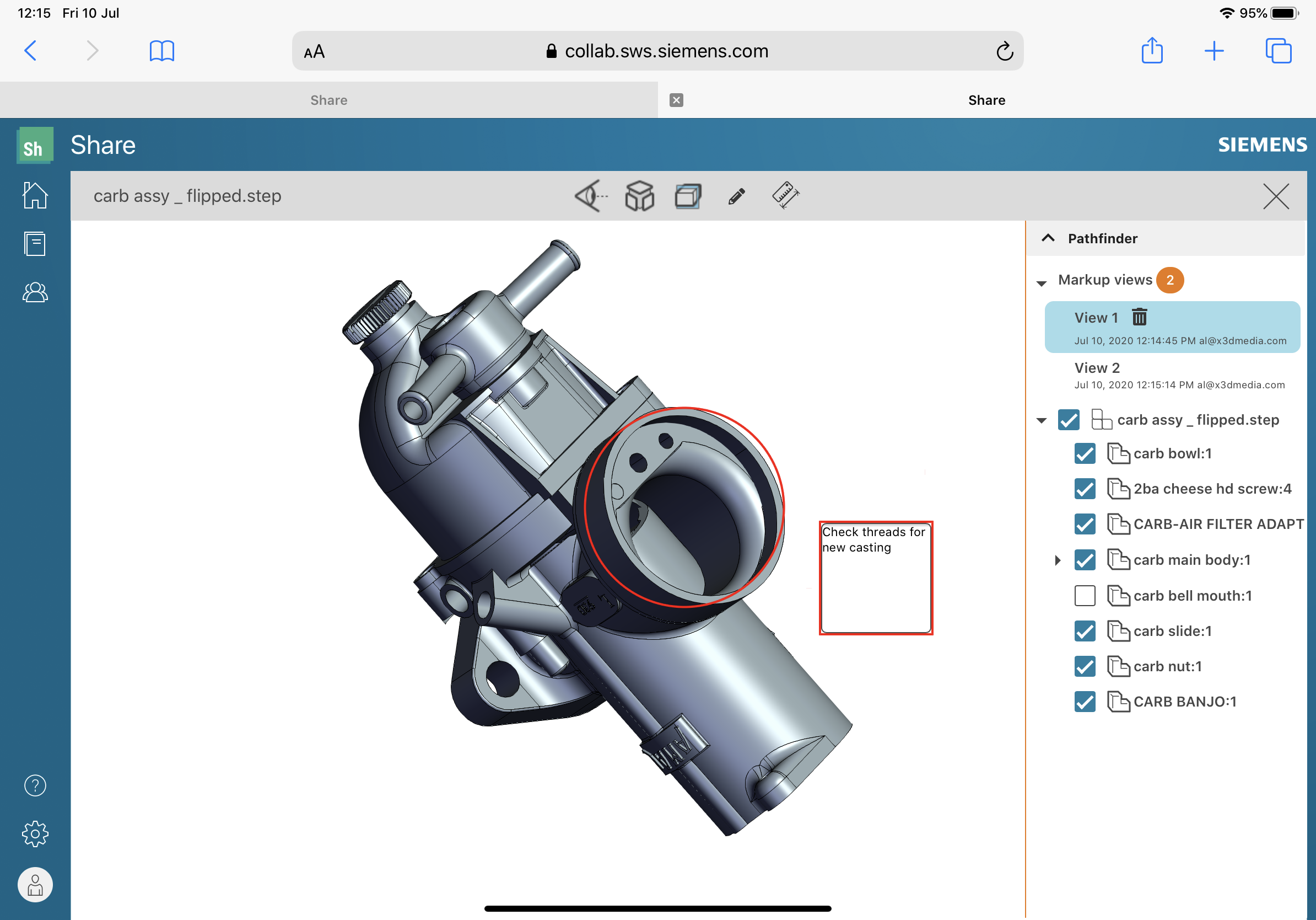
There’s the usual mix of viewing tools: simple view, rotate and zoom; assembly structure exploration; and part visibility, sectioning and measurement capabilities.
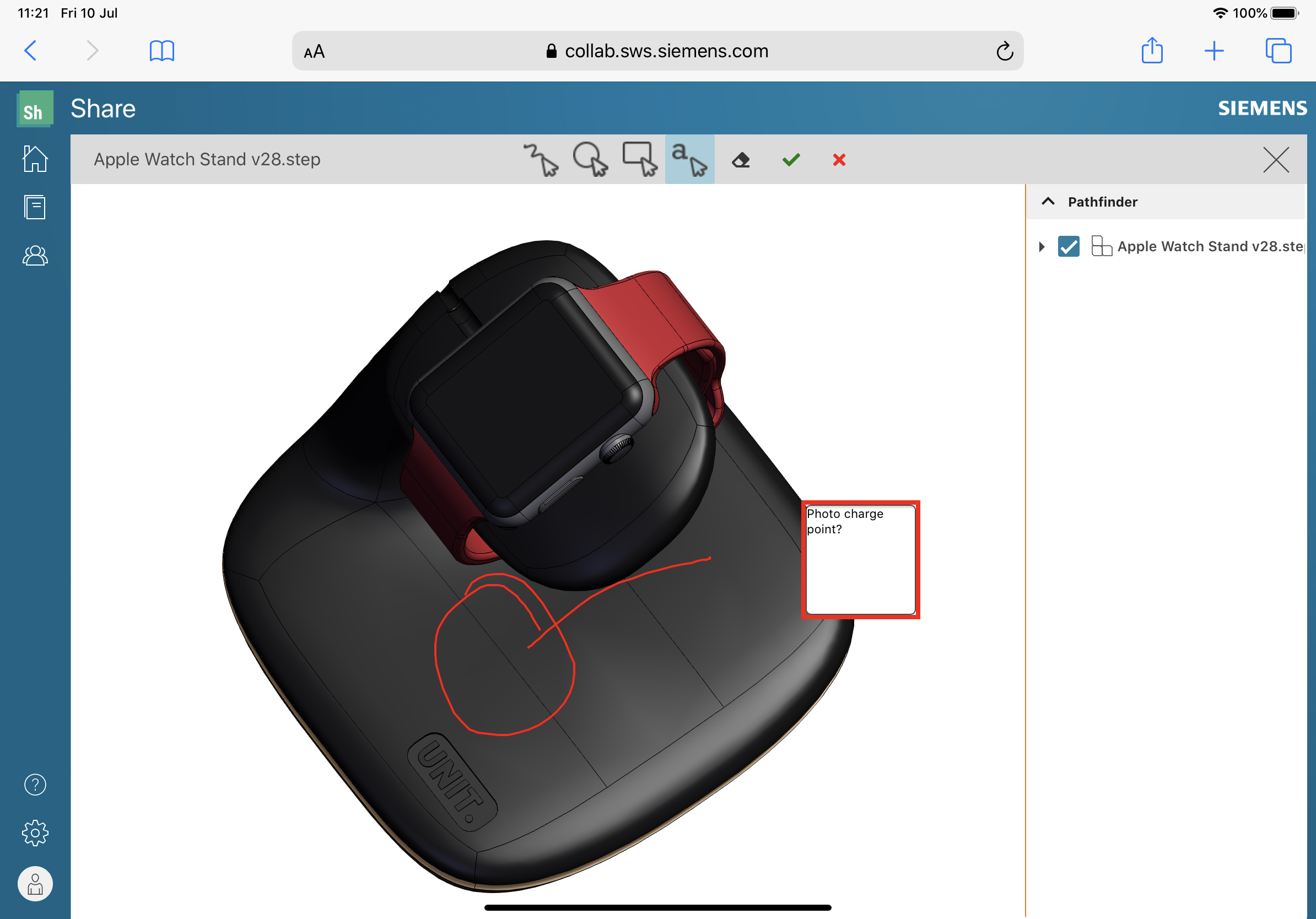
The redline and mark-up capabilities allow you to mark up your model and add comments. These are tagged to your model and available to view by anyone else who has access to the project files.
What’s interesting is that because this is browser-based, you can perform these tasks on pretty much any device that gives you access to the system – whether that’s a lower-end laptop, a smartphone or a tablet. For non-technical staff, this is a neat way to get access to 3D data visualisation tools without a heavy overhead.
If the device you use is AR-capable, meanwhile, you can use it to position the model in the real world. The system uses a detected surface to place the part (on the desk or on the floor, for example) and you can then walk around the object, using your device as your viewing tool. By default, your object is imported at 1:1 scale, but this can be adapted with a quick two-finger ninja move, in order to scale up or down as needed.
The service is currently in beta testing – you can sign up for it here. As yet, there are no confirmed details with regards to price and availability.