

Solid Edge is Siemens PLM’s mainstream engineering and design solution, intended for small and medium-sized businesses (SMBs) – and those are Siemens’ words, not ours. By contrast, the company’s NX toolset is firmly targeted at large-scale enterprises.
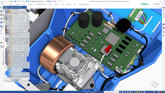
Solid Edge 2019 sees the product portfolio go both broader and deeper
That said, we’ve found that the line between the SMB and the enterprise customer is often blurred. In other words, a choice of toolset is not always clear-cut and can’t be defined by company size alone.
In fact, Solid Edge covers a lot of bases and continues to acquire an expanded set of add-ons, often through acquisition, as we’ll discover shortly. These take it well beyond its traditional areas of focus: part, assembly and drawing creation, with add-ons for simulation and manufacturing.
But first, let’s begin with where things stand with the core tools and what’s new, enhanced and upgraded for the 2019 release. (Yup, the numerical naming convention has been dropped, in favour of using the year.)
Solid Edge – core design tools
There hasn’t been a great deal of work done on the core modelling tools – but let’s be honest, with the combination of Solid Edge’s existing history-based modelling and Synchronous Technology, the product already boasts a pretty rich feature set. That said, there’s always room to add in functions that take time out of processes.
A good example is the new auto-simplify operation. This allows you to grab a part or an assembly and create a solid geometric lump that represents the external shape of that part or assembly, but gives away none of the internal details.
If you also want to remove feature details, this is also possible, but it’s an additional step, using existing tools to de-feature your model. What’s interesting is that this ‘simplified’ version of the geometry is held alongside the full-feature version, so could be used to lighten the load when opening up a large-scale assembly.
Another core modelling update that I personally loved – and one that is related to the update explained above – is the ability to find an interior volume of a set of geometry.
This is the type of process that’s difficult to do, but is absolutely essential for some downstream processes, whether that’s simulation (for a flow domain for CFD) or manufacturing (for core design for casting purposes).
Siemens has also demoed a nice little example that combines this function with the goal-seek tools, so you could iteratively find the fill volume in a liquid container.
The last core update I want to cover is the introduction of a new tool to assist with costing of parts, and specifically, sheet metal parts. For a long while now, Solid Edge has had a reputation for being strong in sheet metal design and documentation.
It’s something that many systems claim to address, but rarely to the satisfaction of those users who live and breath it.
This new costing module will allow you to draw up a costing breakdown of your sheet metal, in real time. It uses a combination of part analysis in terms of material choice, profiling (with laser or waterjet, for example), punching, bends and so on, to arrive at a breakdown of what a part might potentially cost. It’s all based on information that you supply to the system yourself, so you know you’re not relying simply on a software vendor’s best guesses.
But perhaps most interesting of all is the real-time nature of it. With this module sat running in the sidebar, you are able to make live design and materials choices and get real-time feedback on how different decisions might influence cost.
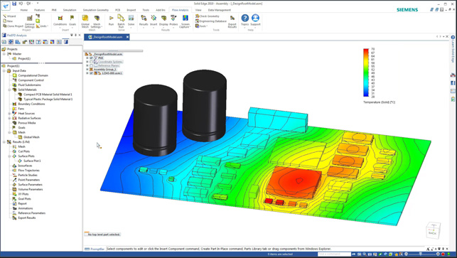
Solid Edge 2019 gets a slew of new tools for both PCB design as well as simulation
Convergent modelling updates
The previous version of Solid Edge introduced its iteration of Siemens’ Convergent Modelling technology. In short, this allows the user to bring in mesh-based data and use it alongside other, more traditional geometry, such as solids and surfaces.
What is most interesting is that the system allows you to carry out featurebased operations on your mesh, once it has been imported or created, enabling you to add geometry or remove it – all of which is tracked in your part’s history.
Another key part of the technology is another set of tools that allow you to import those meshes and both repair and repurpose them – something that can be applied equally to reverse engineered (laser scanned) geometry as it can STL imported geometry.
This toolset has seen some work and extensions for the 2019 release. Firstly, there’s a nice and simple smoothing operation, which allows you to smooth out the surface of your mesh to achieve a more useful result. This can be applied to either a complete mesh or a selected subset.
You also have control over the amount of movement allowed for the vertices and the number of passes that the system will take.
As ever, this is a trade-off between perhaps losing the original shape and gaining a more useful one.
Of course, once you have a convergent part complete, chances are that you’ll want to add it into an assembly. In previous releases, this could be a little problematic, but 2019 fixes this with analytic face recognition. This identifies common face types (planar, cylindrical and so on), which can then be used as the basis for assembly mating conditions. Of course, with meshbased data, this isn’t always an exact science, so there’s also control over the process in terms of the tolerance to which it works.
The final convergent modelling update I wanted to cover was the ‘replace face’ tool. I’m pretty sure we’re all familiar with how this works: You have a face on a solid model and a reference face. Rather than remodelling the existing geometry so that the solid matches up to it, you use a ‘replace face’ operation to swap them. It’s a pretty niche operation, but one that saves a huge amount of time and clumsy work-arounds.
What Siemens has done is extend this operation (which is by no means unique to Solid Edge), to work with mesh-based convergent bodies (which most certainly is unique).
The applications for this are pretty wide, but a couple that come to mind are patient-specific implants and modelling up to CT or MRI data represented as a mesh, or modelling hard surfaces up to reverse engineered forms in the aftermarket automotive parts world.
Solid Edge – generative design
I’m going to try to ignore the fact that Siemens is still calling these tools ‘generative design’ – they’re not, they’re topology optimisation tools – and take a look at what the company has done for the 2019 release.
As you may be aware, this toolset is based on Frustum’s technology, so Siemens is led by what that company does at the back-end and then exposes the same updates within Solid Edge. In the first release, we got a basic set of tools, but without much in the way of control over results or adding in more comprehensive load cases.
For 2019, this has changed on several fronts. Firstly, and perhaps most importantly, it’s now possible to add in a factor of safety, based on yield stress.
This isn’t an additional check. Rather it’s a measure of how much the system can reduce the mass of your part, while confirming to the multiple of the yield stress, rather than an explicit mass reduction target.
Another key update here is the ability to add in multiple load cases. The first release allowed you to add in one, but as we’re all aware, it’s uncommon for parts to experience just a single, static load case.
This allows you to add in a set of maximum loading conditions for your part, to ensure that it’s optimised for a realistic scenario, rather than a singular, idealised case.
Lastly, the so-called generative design tools now get manufacturing controls, so you can specify a vector or plane from which no undercuts can be formed, meaning your resultant part is much more suitable for machining and/or casting.
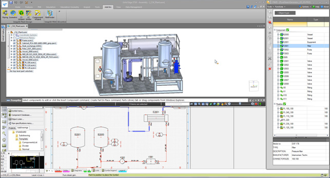
Solid Edge now has a good set of piping and plant design tools, for 2D layout, as well as creation of richer 3D models
Rise of the add-on
Since that just about covers the updates to core parts of Solid Edge, let’s move on to what’s happening with regards to add-ons to the system. The reality is that if Solid Edge is to grow its capability, the most sensible way for it to do that is to take advantage of the wealth of technology available in the Siemens PLM portfolio (which now includes, among others, Mentor and CD Adapco, to name but two.)
To date, we’ve seen the addition of the likes of Flo/EFD, another for Technical publications and CAM. But Solid Edge 2019 sees this ramp up quite dramatically, with a fair few name changes and consolidation, in order to bring some consistency to the branding of these add-on modules.
So this seems a good opportunity to rip through them, explain what they do, what’s changed and, if they’re brand new, explain where they’ve come from and the intent behind them.
Solid Edge Simulation: This is perhaps one of the longest standing add-ons in the Solid Edge portfolio. It provides the expected range of structural simulation tools and is fully integrated into the Solid Edge user interface.
As you’d expect, it’s based on knowledge and technology from Femap (an industry standard pre- and post-processor for FEA) and runs on the NX Nastran solver, so you know that the results are well-validated in terms of reliability. This release sees some work done on meshing, as well as support for transient thermal analysis.
FloEFD for Solid Edge: As you might have guessed, this is a fluid dynamics and heat transfer counterpart to the FEA tools we just discussed. This module is built on technology from Flomerics (which came as part of the Mentor acquisition).
This release sees some work done on how the system handles the simulation of both lighting and radiation simulation. It’s also worth noting that this is one of the modules that will really take advantage of the new PCB import tools that we’ll cover shortly.
Another interesting update is the ability to conduct free surface simulation. This is one of those more esoterically named simulation technologies, but the basics are that you can now simulate how fluid sloshes around inside a containing volume.
It’ll be really useful for those working on material handling projects where distribution of centres of gravity are a major concern. (Think, for example, of tanker trailers that need to turn corners sharply or brake abruptly.)
Solid Edge P&ID: 2019 sees the introduction of a brand-new set of tools intended for those working in plant design. These are to be found in two new products or modules.
Solid Edge P&ID is a new standalone application that provides a 2D schematicbased flow diagram environment for generating flow diagrams using a familiar set of standard symbols (the P&ID industry benefits from some pretty well-defined standards).
Once complete, a diagram can then be handed off to the second product, Solid Edge Piping Design, as a PCF format.
Solid Edge Piping Design:This is a Solid Edge integrated module that allows you to read in the Isogen-based output from Solid Edge P&ID and start to build up a 3D representation of the plant work, allowing you to carry out all of the additional routing and supporting work needed to prepare a plant design for commissioning.
Interestingly, there’s a lot of intelligence here, so the system is aware that while you might have common pipes oriented or flex differently across your project, the system will maintain the part number, so your BOMs remain up to date.
It’s also worth noting that both this and the 2D schematic product are available in their own product configurations, which means that if you’re solely interested in these parts of Solid Edge, you can licence them without the need for all of the other bits and bobs that aren’t really required.
Solid Edge PCB Design: This is the first of a couple of electronic/electrical-related additions to the portfolio. As you might guess, all of these additions are based on Mentor technology and existing products.
Solid Edge PCB Design focuses on the development of PCB boards and, again, is split over two products.
The first is a schematically-led layout tool that runs on the browser. It includes both a 2D and 3D view, allowing the PCB designer to develop a pretty rich description of the PCB and associated components, according to their requirements and workflows.
A collaboration file is then created which can be read into Solid Edge and a 3D model constructed automatically, with an associative link back to the originating data.
The systems can rationalise any changes made on either end (for example, moving a component in Solid Edge), as well as capturing any notes made by either party.
Alongside this, if you’re working with outsourced PCB design or supplied data, you’ll also be glad to learn of the new PCB import tools.
These follow the usual conventions of an IDF reader, allowing you to import and construct 3D models from IDX 3.0 files from the likes of Eagle, Altium or other Mentor products).
Solid Edge Wiring, Harness and Electrical Routing: I’ve grouped these three add-ons together, as they are all interrelated and work towards a very similar goal. As with both plant and PCB design, a lightweight front end built on Mentor technology allows the electrical team to define wiring runs, harnesses and more between intelligent components and to conduct their own set of validations.
This data can then be connected to Solid Edge to allow a 3D representation to be worked up, routing functions carried out and information passed back to the wiring schematics where needed. A perfect example of this is that, in the schematic Wiring Design application, there’s little awareness of wire lengths. When that data is transposed into Solid Edge, routed through a full 3D model of the product in hand, the length data can be passed back from Solid Edge and a more complete representation becomes available.
The two systems work in an associative manner, so changes made in either system can be propagated where needed. If you’re conducting design reviews in real time across a network (using the connected mode), then there’s an instant feedback.
Where the electrical team highlights a set of wires, the same is highlighted in Solid Edge, making those collaborative sessions all the more efficient.
Solid Edge CAM Pro:This is a rebrand of the CAM Express add-on for Solid Edge that has been around for a good decade or more.
If you’ve not come across it, it’s essentially the basic 3-axis CAM and basic turning functionality from Solid Edge’s enterprise-focused cousin, NX. It’ll work with Solid Edge just as easily as it’ll work with data from other native systems. There haven’t been too many changes to the product, other than the renaming and some additions relating to both how the system handles PMI with feature-based tolerance data (it can read it in and use it as the basis for feature recognition in a making context) and some new adaptive roughing operations.
Solid Edge Technical Publications: A few releases back, Siemens introduced an integration between Solid Edge and QuadriSpace’s technical publication toolset.
This continues with this release, but with a couple of key updates. The first is that that there’s a great level of association between the two systems, meaning that while your tech pubs team can start generating your technical documents long before design and engineering is frozen, you can also ensure that any subsequent design updates are quickly propagated in the documentation.
Solid Edge Requirements: This is the last new add-on that we’ll cover today and personally, I think it’s a cracking bit of kit.
The background to this comes from Siemens ALM tools (that’s Application Lifecycle Management to you and me) and allows you to quickly capture, organise, share and document your projects’ requirements.
Solid Edge Requirements comes in the form of a cloud-based service, built on top of Siemens Polarion.
This means that you can have sales or technical consultants in the field, capturing requirements related to a project. Then, the designer or engineer can access this data through the Solid Edge interface, fulfill those requirements, make comments, and finally, tag the resultant data to each requirement.
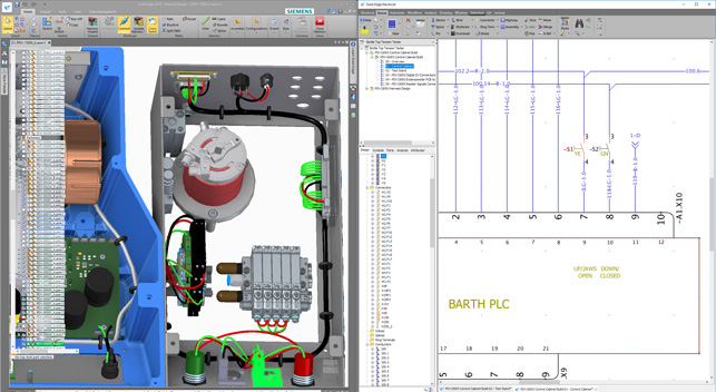
The new Solid Edge Wiring Design tools allow specialists to develop schematically led wiring diagrams, that then feed that data into Solid Edge
Data management
Let’s round things out with a look at what’s happening on the data management front.
As those that follow Solid Edge will know, in the last few releases, Solid Edge has changed track on its data management offerings for Solid Edge. While previously the company relied on a Sharepointbased solution, it recently retired this and developed a new set of tools that require nothing else except your file system and your network.
Due to some of the changes made in how Windows manages data and some smart thinking from the Solid Edge team, this new data management system works right out of the box and provides the basic data management, revision and release style management that most smaller organisations really need, combined with some enhanced search tools, greater visualisation in terms of thumbnails, and it plays nicely with the likes of OneDrive and Dropbox for collaboration.
In this release, the big change is that you now have greater control over part numbering schemes. At the other end of the spectrum is the Teamcenter and Solid Edge integration.
For a while now, a rapid-start Teamcenter implementation has been offered to Solid Edge users and this continues to grow in terms of integration and support for not only Solid Edge data, but data from other systems as well.
In conclusion
As you can see, the Solid Edge portfolio is growing, and growing quickly. The acquisition of Mentor by Siemens is clearly driving a lot of this and there’s huge potential for existing Solid Edge users to gain a little competitive advantage by adopting a more connected and integrated environment for conducting both electrical design as well as PCB design – particularly for those organisations looking to bring all of these tasks together in house.
At the same time, there’s also some growth in the core modelling tools. Solid Edge’s core set of functionality has been pretty stable and robust for some time now, so we’re perhaps in an age of iteration and incremental improvements, rather than one of true revolution.
That said, the introduction of convergent modelling will certainly prove useful for some. The rise of additive manufacturing also points to potential, although adoption of it as a mass accepted manufacturing technique is still some way off.
The potential of the topology optimisation tools can’t be denied – and the addition of the manufacturing controls means that it can be applied to a much wider spectrum of manufacturing processes than just pure additive.
It’s pretty clear that Siemens is looking to address a much broader group within the average engineering team with Solid Edge than has previously been the case. The product has moved from simply covering the realm of mechanical and engineering design and expanded into the wider world of electronic design and electrical design as well.
That strongly suggests that Siemens is looking to push up the investment that each customer makes in its toolset – it is, after all, a commercial organisation that needs to make a profit. But looking at each of these individual parts and the manner in which they’re connected, the thinking here makes huge sense.
You can offload the schematic and theoretical work to the specialists, but still ensure that the tools they use are connected back to Solid Edge. In this way, data and knowledge can be re-used to build accurate 3D models, and the benefits of that rich 3D representation can be fed back to the schematic world in the form of design changes, more accurate BOM information and much more.
As releases go, Solid Edge 2019 is a good one. Those users who use only the core tools might feel a little short-changed, particularly given the vast swathes of new tools common in previous releases, certainly. But for the average organisation using Solid Edge, this release could hold the key to some real productivity gains and commercial benefits.
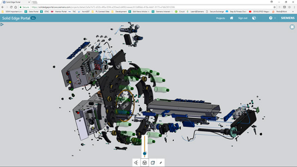
Solid Edge Portal: Data sharing and collaboration
Introduced as a beta with the last Solid Edge release, for 2019, we see the Solid Edge Portal move into production readiness.
Should you not have seen it, this follows the common industry line of, “We’ll give you online data-sharing, in return for your email address.” (Most vendors have a similar offering.) That said, there are some nice tricks here that make it worth exploring for both Solid Edge user and non-user alike.
Solid Edge Portal is a cloud-based file viewing service that allows you to upload data from a wide variety of sources. This covers all native Solid Edge 3D data, of course, plus the usual neutral formats such as JT, IGES, ACIS, STEP, Parasolid, as well as a good selection of native files from Catia (V4, V5 and V6), Inventor, NX, Creo, Rhino, SolidWorks. It’ll also open up drawing files in both DWG and Solid Edge’s dft format.
Then, interestingly, it also supports non-CAD files including images (the usual bmp, jpg, png, svg) as well as office-type documents, including word docs, text files, spreadsheets and presentations.
Sadly, there’s no PDF viewing option. The system allows you to organise data on a project basis, upload data by dragging and dropping, and gives you control over who can do what with data (view only, or view and download). The view and mark-up tools are as you would expect (most vendors use TechSoft’s HOOPS technology as the basis of their variants), so you have a good selection of view, rotate, explode and so on.
There are commenting and red-lining tools available, which are tracked and made available to everyone sharing the same project – all in a nice clean interface.
Every user gets 5GB storage with their accounts, making this a pretty efficient service, particularly for one that’s free.
| Product | Solid Edge |
|---|---|
| Company name | Siemens |
| Price | on application |


