

nTopology 3.0 – Built-in simulation tools and newly added GPU acceleration make this software a definite must-have for any team looking to flex its muscles in simulation-driven design, writes our reviewer SJ
Some designs are just too complex to create using conventional CAD programs. That’s the thinking behind the nTopology platform from nTopology.
This resonates. As a black woman in engineering, and now in additive manufacturing, I understand the scrutiny and pressure to constantly go above and beyond expectations just to be considered as good as everyone else in the room. So I’m constantly looking for ways to make my designs for additive manufacturing really stand out.
As my mother always tells me, “Birds of a feather all flock together.” After reviewing nTopology 3.0, I can confidently say that I’m flocking with nTopology.
Before we even open the programme, let’s break down the problem we’re trying to solve. As a real-life example, I’m currently working towards lightweighting a pair of skateboard trucks.
With conventional/explicit modelling (for example, in Solidworks or Fusion 360), I could achieve this in a variety of ways. The easiest method might be to use generative design or topology optimisation modules that already exist. This requires the designer to make a design change and then run the part through an FEA-style analysis, to ensure it won’t fail under critical loading conditions.
If it doesn’t fail – then yay! We move on to manufacturing. If it does fail (as it so often will), then I’ll need to play with the geometry or the material settings in iterative trials until I get it right.
Which kinda sucks, because Fusion 360 requires me to pay for a set of tokens any time I want to use its generative or topology optimisation modules. The costs can add up really quickly. As an added bonus, the Fusion solver is run in the cloud and can sometimes take hours to compute before I get a result.
Solving a generative design problem shouldn’t require engineers to run ‘set it and forget it’ computations. It should be as instantaneous as punching numbers in the calculator. This is the pain point. This is the frustration that nTop can eliminate, with computations that run in mere minutes, not days.
nTopology 3.0 – Getting started
First, a few words of advice upfront: NTopology is an acquired taste, like sushi, or wine and charcuterie. Do not go into this expecting your typical Solidworks or Fusion 360 layout or design process.
And now, I’m going to say outright what everyone has been sort of tiptoeing around: the nTopology design process relies on modifying existing CAD geometry, using long algorithms of advanced computer code.
(Yes, that’s right. They’ve tricked us all into somehow liking computer science. I honestly wish that coding had been presented in such a straightforward and easy manner back when I learned computer science.)
So, let’s break it down. As with most coding, you don’t have to start from scratch – there’s always a base workflow to get you started. The success team at nTop does an excellent job at this, providing a few basic notebooks that you can download from the company’s site for free.
I’d highly recommend that most beginners start here. The notebooks are well-documented and it’s fairly straightforward. Before we get in too deep, let’s take a quick look at some of the terminology at work here.
A variable in nTop is very similar to the ones we know from Java and Matlab. It’s any parameter that’s subject to change. You can convert any block into a variable, and I’d recommend this if you plan on reusing the contents of the block throughout your notebook. This can easily be done by right clicking and then selecting ‘Make Variable’.
An implicit body (most commonly nicknamed ‘implicit’) is a 3D geometry represented by a distance field. When you convert an explicit CAD model from Solidworks or Fusion into an implicit, the part is no longer represented by the concrete surfaces, edges and vertices you’re familiar with. Instead, the part is converted into a system of mathematical equations that represent the geometry of your part. These equations (or fields) are more robust as a data file and take less time to compute.
A mesh is like a net that wraps around your part to define the vertices, edges and faces of an object.
When you open the software and start a new project, on your left opens you’ll see a notebook open. The purpose of this notebook is to help designers document, group, comment and organise their workflows. I like to think of the notebook as a literal piece of paper where I describe my process for modifying a geometry.
Finally, there’s blocks. nTop successfully hides all of the anxiety-inducing hard lines of code and condenses them into blocks, which contain functions that operate based on given inputs from the user.
nTopology 3.0 – Putting nTop to work
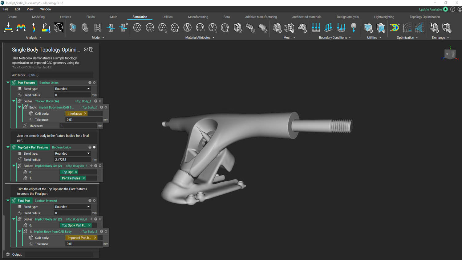
Let’s return to my example for lightweighted skateboard trucks. The workflow recommended by the nTop support documentation is to first import the CAD file; then convert the CAD to an implicit body; and finally, to shell it and fill it with a lattice.
Let’s break down those three steps in more detail. The first step to almost every Notebook is to import the CAD geometry you want to optimise. NTop works best with Parasolid files (think .step, .iges or .x_t), but it also accepts native CAD geometry files from most programmes.
Next, that CAD is converted to an implicit body. This step is important, because it’s less labour-intensive and time-consuming for the software to run computations on these implicit bodies.
Implicit models can be queried in an infinite number of ways, without the application needing to recalculate the solution each time. This delivers optimised processing speeds, providing a new model in a fraction of the time.
When it comes to modifying your implicit geometry, you can run operations like Booleans, offsets, drafts and rounds simultaneously. Here we see one of the biggest ways in which nTop differs in its approach to design. Instead of making a change and waiting for your CAD tree to update, you can make several changes and they all update at the same time and in real time.
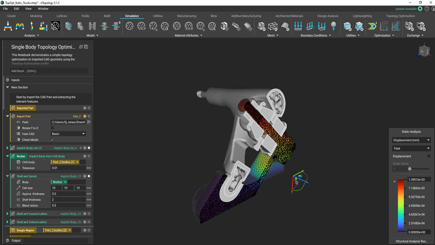
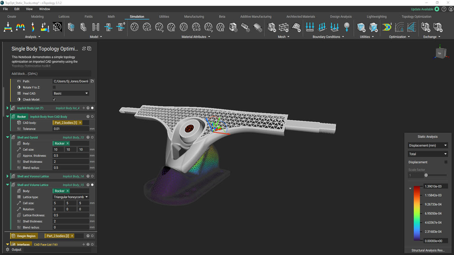
Finally, the third step: Shell and fill with lattice. In the latest release, nTop has updated its lattice pipeline to include new blocks: Periodic Lattice Body block (beta), Custom Implicit Unit Cell block (beta), TPMS Unit Cell with Bias (beta), Orient Unit Cell block, Voronoi Volume Lattice Body (Beta).
For the purpose of the lightweighting, however, nTop already has a custom block for operation, so it should be fairly straightforward to just tell the application what you want and… Bam! Done in under 60 seconds. You can see the results in Figure 2 .
Getting results
I didn’t even have time to stretch before the application had finished solving and generated my part.
The new nTop update to GPU acceleration means rendering is between ten and 100 times faster than in the previous nTop version. The updated user interface allows you to make real-time edits to any scalar value at the click and drag of a mouse, providing you with dynamic, instantaneous feedback.
What’s great here is, without doubt, the ease of use. Designing in nTop is akin to driving a Nascar. You get fast-paced, robust, highly optimised performance. That said, you do need to take some time to understand what you’re doing before you start out. nTop isn’t like most engineering CAD programmes, where you enter the display window and start pressing random buttons until something generates. Its purpose is to solve complex engineering problems. For that reason, your task should be approached as seriously as one would approach the challenge of professional racing.
Another big bonus is quality: this software offers best-in-class lattice generation tools. The lattice application is fast, powerful and responsive, providing visual feedback as you navigate workflows.
The website also provides a customer portal with supporting documentation that’s easy to read and understand, as well as pre-built notebooks to help designers get started. Customer support is fast and responsive via email, web, or Slack.
As a user, I also appreciate that the newly updated error/warning messages in nTop 3.0 give you helpful hints as to what you may be doing wrong, so you can troubleshoot independently.
And with the new GPU accelerator, the tasks of saving, closing and reopening notebooks also feels faster. That sounds like a small thing, but when you’re the engineer on a Zoom call who has to present your design to a wall of faces, you can feel more confident and at ease knowing your rendering is reliable and fast.
Who and when?
To answer the question ‘Who’s it for?’, I think it’s just as important to think about, ‘When’s it for?’ In other words, how do you identify the best stage of the process for you, or someone on your team, to put nTopology to work?
In my opinion, the application has the greatest impact at the concept stage, where it can be used to create generative designs based on engineering knowledge. Those designs can then be exported from nTop into traditional CAD programmes, in order to enter the company’s product development workflow.
From the CAD stage, the part moves on to manufacturing, where members of the manufacturing team – or those working on the shop floor – can easily feedback the results to the product development team. This allows for faster design changes, more iterations and a quicker time to market.
Although it makes more sense to me to start with nTop at this early stage, I’ve more commonly seen nTopology used at the stage that lies between the CAD phase and manufacturing. This is a typical workflow for companies that are structurally optimising already-existing parts using the nTopology platform.
So to focus in on the ‘who’ question: everyone who touches the product during development should be aware of nTopology and knowledgeable in how it works.
This includes subject matter experts, specialising in software like Ansys or Abaqus, who typically focus on simulation. They will most likely find nTop incredibly intuitive and experience a shorter, faster learning curve.
It also includes application engineers in charge of product designs, who will benefit from being able to automate their workflows to come up with a series of designs that can be tested quickly.
And it most definitely includes manufacturing engineers. Just because a part is organic in shape, this doesn’t make it easily manufacturable – and for that reason, I strongly recommend nTopology to this group. In my view, it will enable them to offer better input to product designers and shorten the time it takes to send feedback up the development chain.
nTopology 3.0 – pros and cons
I found much to praise in nTopology 3.0. Its built-in simulation tools make it easy to perform design analysis, and the results of this analysis can then be used as an input to drive part geometry. With GPU acceleration, it becomes faster and easier than ever to design, simulate, and export parts.
Best thought of as an engineering tool – not a CAD programme – nTopology is a programming language perfectly suited for engineering design. The advanced geometry kernel based on their implicit modeling method creates unbreakable geometries.
With the new release, nTop continues to hold the title as the greatest at advanced, complex geometric structures such as lattices and gyroids.
Alternatives to nTopology include conventional CAD systems such as Siemens NX, Fusion 360, and Solidworks. Additionally, applications like Onshape, Rhino, FreeCAD, and Grasshopper 3D are also candidates for generative design.
Most of these more conventional programmes far outstrip nTop in terms of wide acceptance and faster learning curves, but they can’t compute anywhere near as quickly, nor do they offer the same level of performance in terms of implicit modeling or lattice generation. I’ve used Siemens NX to generate similar lattices to nTopology, but the render was incredibly slow and my part file became so massive that exporting it required me to leave the laptop in the office to run overnight. In terms of speed, customisation, design automation and workflow offerings, nTopology can’t be beat.
In terms of cons, nTopology is still finding its place in legacy engineering workflows. If you’re in a rigid, legacy company that expects both a solid part (not just an STL) and a drawing to be released before the part can head to production, nTopology may have difficulty garnering acceptance. It also has a high learning curve and its likeness to coding may scare off the less adventurous.
Conclusion
Whenever I want some new dohickey, my boss always asks me, “Is this something that you want, or is this something that our team needs?” Normally, the answer is a grumbled “Never mind”, but in the case of nTopology, it’s a definitive team need, especially as an additive engineer.
Additive manufacturing allows us to print shapes and geometries that conventional manufacturing can’t achieve. It’s faster to market, materials can be locally sourced and lead times can be cut from almost a year to just under four weeks. Now, imagine what additive could achieve when used in conjunction with a software that iterates and designs just as quickly?
The goal of nTopology is to offer the most advanced engineering software in the world. With a team composed of experts in geometric modeling, computational mechanics, advanced manufacturing and computer science, the company is successfully setting the standard while simultaneously exceeding the limits of simulation-driven design.


