
The combination of the latest optical scanning techniques, ‘mesh to CAD’ processes and FEA model generation is enabling Raptor Titanium to attack the market with deadly accuracy, writes Dr Steffan Evans, CEO of Evotech CAE
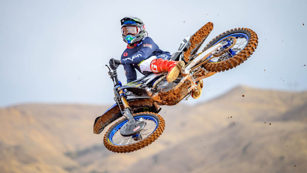
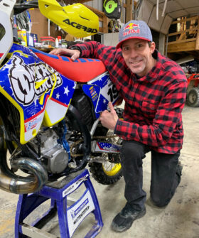
Motocross, enduro racing and FMX (the freestyle version of motocross) are some of the most dynamic and action packed wheeled sports around today. They also put motorcycles in situations that far exceed the performance capabilities of their road-going counterparts. Modern-day ‘Evel Knievels’, such as the legendary stuntman Travis Pastrana and his Nitro Circus counterparts, regularly amaze audiences, literally defying death with their feats. In replicating Knievel’s iconic jumps over multiple cars and buses, and the odd Caesars Palace fountain or two, failure is not an option – for either the rider’s nerve or the bike structure’s on impact.
One company crucial to all of this, Raptor Titanium, is based in Barnoldswick, Lancashire in the UK. The company’s titanium foot-pegs have gained a worldwide reputation for delivering the kind of performance that Pastrana and fellow extreme athletes demand.
Raptor Titanium had its beginnings in the aerospace industry, supporting the welded manufacture of titanium fan blades used in some of the world’s most powerful jet engines, but moved over to foot-peg manufacture through a general love of all things motorcycle, and some pretty fancy-schmancy welding technology (all top secret, by the way).
Today, with over 20 years of top-notch manufacture, the company supports numerous elite professional teams (think KTM Red Bull, Kawasaki RT and Rockstar Husqvarna, to name a few), along with title-winning riders, such as Patrana, Clement Desalle and Tony Cairoli (all multiple X-games, GP and world title holders).
Raptor Titanium – Testing aggressive design
Historically, Raptor Titanium has used significant in-field testing to develop its aggressive designs. This has been based around rider feedback, coupled with a smattering of practical lab testing, involving dropped masses to replicate the impact loads seen during riding. Combined with the multi-year warranty that Raptor issues with every set of pegs, a breakage is painful at the very least, and can be catastrophic at worst.
Over the years, development has been a slow, incremental process, based on subtle changes to design, manufacture and material choice. With a growing customer base, market competition is always biting firmly at Raptor’s heels, whether via design infringement or lower-cost, inferior manufacture.
At Evotech CAE, we were introduced to Raptor Titanium through an industry-focused development initiative to upskill companies, in the light of the ‘new normal’ for UK manufacturing that Brexit, Covid-19 and other market factors (such as raw material usage and supplier lead times) have brought. Initial conversations were based on a desire to reduce development time and improve product performance through digital technologies.
With our background in advanced FEA, this was a perfect fit for our skill set. Many readers will see this an obvious step, but a carefully considered simulation strategy could make a massive difference to Raptor Titanium, both in simply better understanding its product (and warranty) and allowing future optimisation.
Raptor Titanium – Optical scanning at work
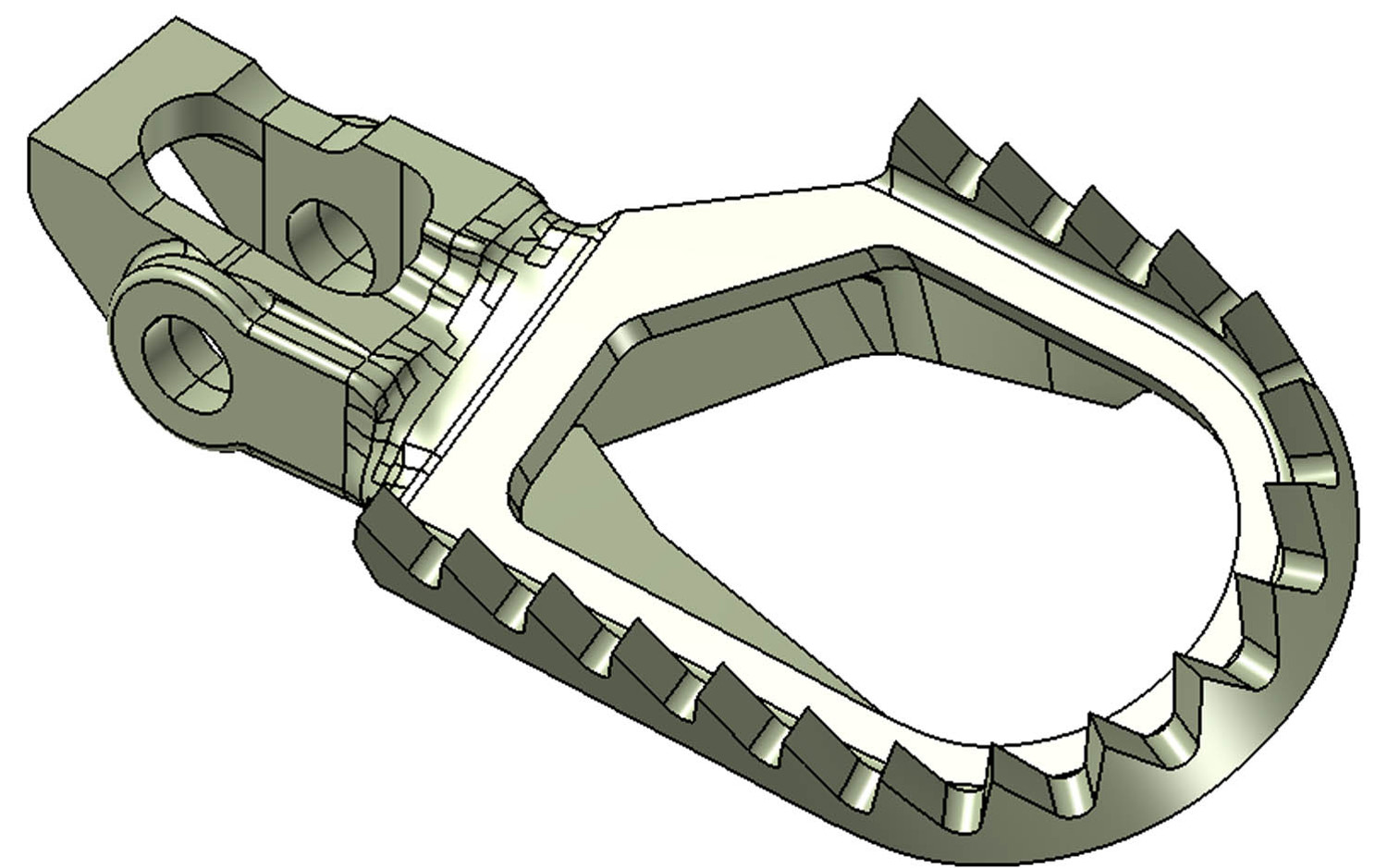
The first stage of this strategy was to obtain reliable 3D geometry of the foot-peg form. The assembly was made up of a series of CNC’d titanium parts, with press-formed ti plate, welded together with Raptor’s ‘secret sauce’.
Sure, CAD data existed representing each of the component parts, but there was no fully welded CAD model, with all the organic intricacies of the smoothed weld geometry. This was where scanning and reverse engineering came in.
Through an existing Raptor Titanium relationship with GOM UK, we were able to generate the necessary STL data to give us a starting point for reverse engineering. It’s at this point that I have to say I learnt a huge amount about the scanning process, and the ability to generate usable CAD for downstream processing.
I would say I was naïve in thinking that you just point the scanner, generate the point cloud, then hey-presto, there’s your CAD. It’s not quite as simple as that, so let me explain what was involved.
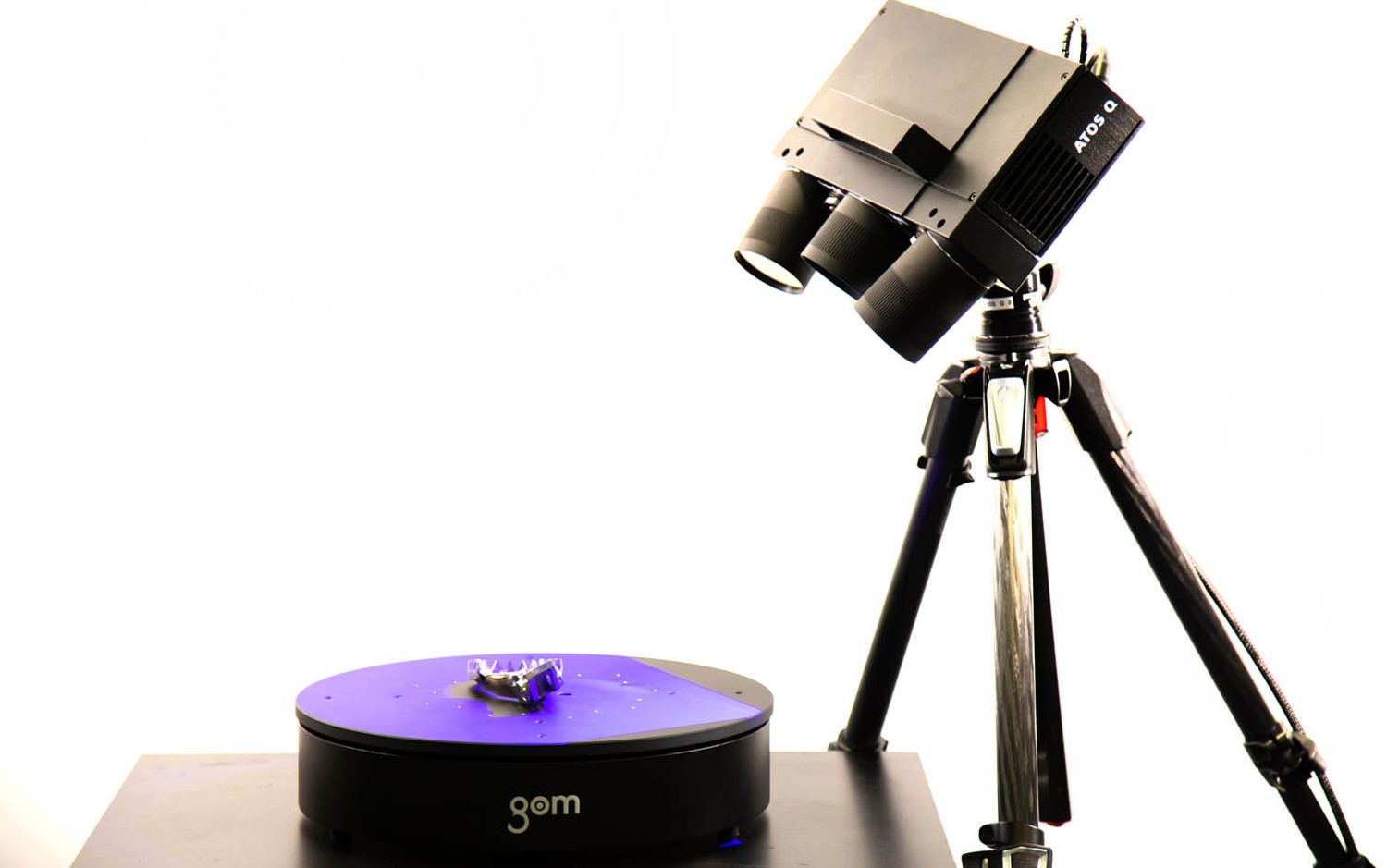
GOM UK utilised its latest ATOS Q 12M digitising system, which utilises ‘blue light technology fringe projection’ and two stereo cameras, to capture high-quality point cloud data of the part. An automated rotation table was used to assist the positioning of the part in different orientations for the cameras – rather like you might orientate the part to your eyes to observe the different surfaces. The supporting software, GOM Inspect Suite, brought the data together, with feedback to the user on the data captured.
There were a few issues with line of sight, where the cameras simply couldn’t reach some of the undercuts where parts came together. Sure, existing 3D geometry would have given us a heads up here, but instead, we used the geometry processing capabilities of the GOM Inspect Suite software to fill in the gaps and generate planar sections required to rebuild the clean geometry.
Reverse engineering in progress
MSC Apex uses a state of the art Parasolid geometry kernel for FEA model development. Fundamental to this is the ability to create and manipulate geometry in many forms. There are tools in Apex which easily match or surpass the most powerful CAD software on the market today, and all within a CAE/FEA platform.
One of these workflows is the ability to reverse engineer legacy FEA mesh data into a form that can be redefined for a new model, whether that’s to add additional structure or to look at different analysis strategies, such as submodelling. A by-product of this ‘mesh-to-CAD’ workflow is the ability to reverse engineer imported STL scan data into NURBS geometry.
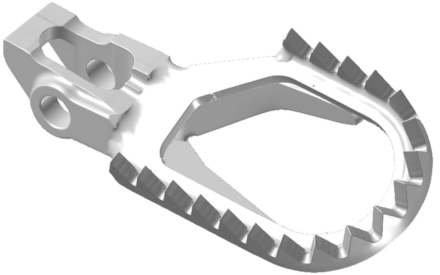
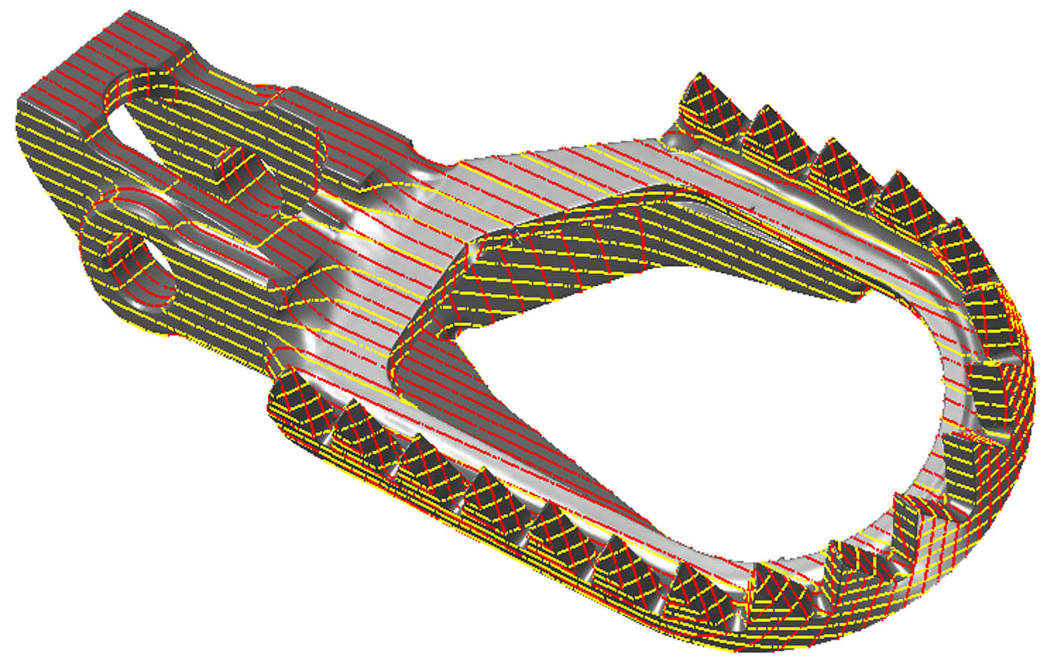
We used these tools to rebuild the geometry from the STL point cloud and the section curves that GOM Inspect Suite generated. The section curves were used as construction geometry for the standard NURBS primitives (planes, cylinders, spheres) for the machined regions, where it was easier to understand the design intent or shape in the structure. The more organic regions (historically more difficult to handle, especially at the weld interfaces), were represented with double-curved patches which were lofted using shape constraints into the machined region interfaces.
Once the geometry has been recreated, we were able to use GOM Inspect Suite to compare with the original STL definition, both in terms of visual overlay and enclosed volume. The overlay showed a high degree of accuracy, especially at previously critical structural features.
The calculated volume of the NURBS CAD was within 1.7% of the original STL form. We also checked the left/ right comparison for a pair of pegs to understand any manufacturing variance, and its impact on the downstream analysis. Any differences were shown to be tiny, and well within the ‘noise’ of the resultant FEA. A side benefit of the CAD geometry creation was that Raptor also had reliable assembly CAD for its CAM and inspection processes.
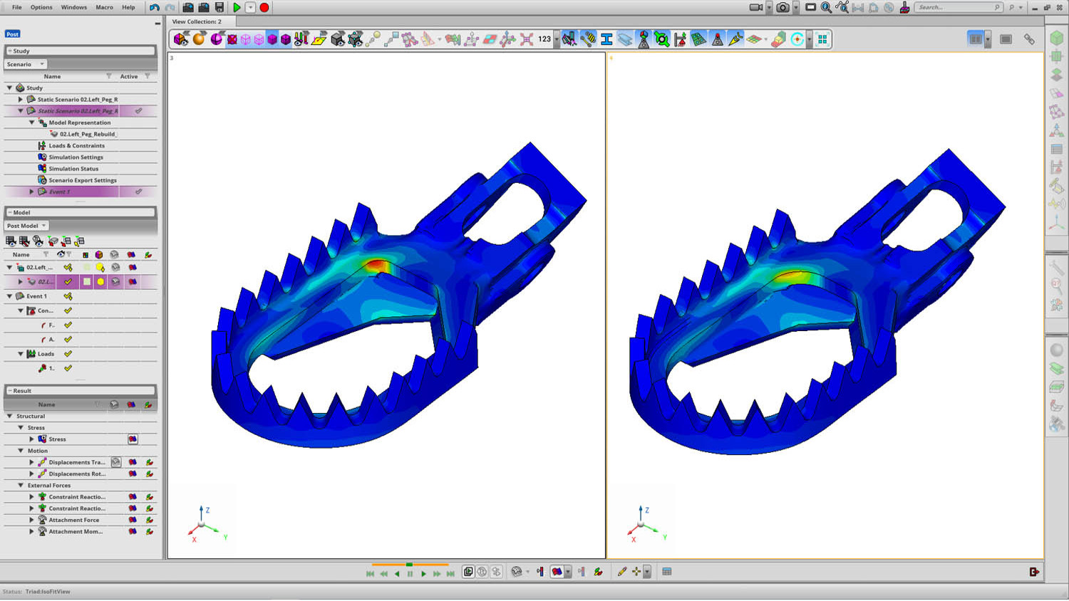
Moving into FE analysis
Once generated, the NURBS geometry could be 3D meshed (using 10-noded Tet elements), with the appropriate automatic feature controls on fillets, faces, hole washers and cylinders. An iterative mesh convergence study was performed using the embedded Apex ‘generative update’ tools to give the appropriate balance between converged feature-based stresses and model size. Had the resulting model been too cumbersome, then we could have adopted a hybrid solid meshing approach using hex elements, but this was not the case.
We applied unit static and fatigue loading to determine the load to failure in key directions from the material allowable strength. Once determined, this was assessed both in terms of non-linearity and sensitivity to load direction. Given that we had access to NURBS geometry, we were able to show the impact of design changes (such as thinning the discrete plates or changing weld sizes) from a mass and strength perspective.
Raptor Titanium – The road ahead
While the FEA aspects of this project were not particularly ground-breaking, the ‘part to CAD to FEA’ workflow was something pretty new to us. The ability to generate clean geometry in a timely manner, then witness the response, gives at least an order of magnitude of improvement in Raptor’s development process – and all using contemporary software that eased the whole process and made it commercially viable.
So, what does this mean to Raptor? Well, it now has a much better idea of its product’s performance, where the manufacturing and performance sensitivities lie, and what it can do with its next generation of foot-pegs, whether that’s looking at new bespoke geometries, new manufacturing methods (including AM) or new markets.
Reverse engineering has been around for a while, but the ability to use the latest optical scanning techniques, coupled with state of the art ‘mesh to CAD’ and FEA model generation, gives companies both large and small the edge they need in designing the products of tomorrow.
And as I conclude this, I notice that 19 buses have parked up outside my house, blocking the road – and just when I need to go and pick up my son Sol from school. Where’s Travis Pastrana’s bike when you need it?


