For those that are engaged in simulation in engineering, the name Ansys is one to note. It’s been there since the start of the industry and still holds a dominant position for those simulating and analysing their products during development.

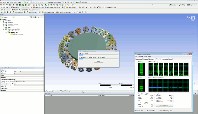
Meshing is now multi-threaded to give better performance when working on complex assemblies
While the long-term users will be familiar with the often command driven classic Ansys interface, the last few years have seen the company focus on moving both its core structural analysis tools (as well as the long list of acquisitions in recent years) to the Workbench platform.
Workbench provides a single interface to all of Ansys’ tools. From the classic structural tools to the various CFD solvers and technologies it has access to (Ansys acquired both Fluent and CFX in recent years) and the more special purpose technologies in its stable.
The goal is to provide a single platform that allows users to take advantage of a more simple, schematic style approach to build simulation tasks.
It’s driven by building up and connecting different building blocks. Each of these blocks allows you to take inputs and outputs from one stage and feed them into the next or indeed, multiple processes.
The clever part is how Workbench is handling the transformation and repurposing of that data.
A good example is using a geometry import handling ‘block’ then using this to feed geometry into multiple solve ‘types’. Any updates back at that initial ‘block’ can then be propagated into those solves,
be they structural linear problems, CFD or indeed, a mix of the two.
It’s a simple, very basic, example, but it shows how the system handles much of the grunt work that analysts could spend days on — just trying to get data from one simulation ‘type’ to another.
So, while we haven’t the room to explore everything that’s up to date and new in this release, let’s step through some of the big ticket items and see where Ansys Workbench is heading with the 15.0 release.
User customisation
Workbench rewrote the book on how Ansys users interacted with the underlying technology, but it’s also the case that longtime users have a lot of experience and knowledge built into scripts, automation routines and other in-house developed items.
The last few releases have seen the ACT (Ansys Customisation Template) environment start to flesh out. This enables users to take their own assets and publish them for others to take advantage of, perhaps bringing them into Workbench as entities on their own or even distributing them publically through an app store like approach.
Large complex models
When it comes to large simulation tasks (in terms of geometry complexity), this release has a few tricks up its sleeve.
Much of this centres on the ability to use the most appropriate modelling technique to solve the problems you’re working on then change it to focus in on details where needed — best illustrated by stepping through the workflow.

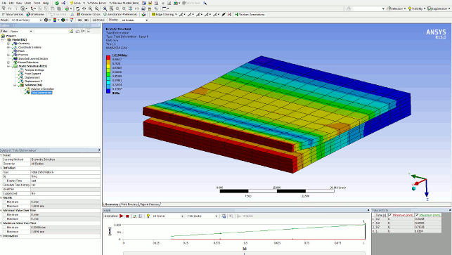
A results set showing how delamination or peel occurs in a composite form
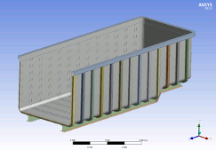
Consider a large, complex model (perhaps of an oil transportation vehicle). Modelling and analysing something of this size using solid elements would require both a huge amount of time to set-up, then to execute.
Luckily, the FEA world gives us some handy shortcuts to idealise such a problem and reduce the overhead of work. By using shell elements (which are essentially 2D elements in 3D space) to represent the various aspects (such as frame, pressure vessel, etc.) in a more lightweight form.
This type of set-up can be simulated much more efficiently, using a coarse mesh across the whole of the product. This, in turn, will give you an indication of where stress concentration exists, where areas of concern are found and where you need to focus your engineering skills.
All this is pretty standard fare in most systems. Where Workbench differentiates itself is by allowing you to focus on those areas, reworking the simulation to create a solid mesh that gives a more holistic description of the effected parts, then ensuring that those loads, restraints and contact conditions defined in the previous study are reused to learn more, in greater detail.
Meshing updates
The big news on the meshing front for this release is that the core meshing tools in Ansys now run across multiple cores/threads.
What’s interesting is how this has changed. In previous releases, it worked in serial, meshing the first part, then the second, then the next — and so on. Now, Ansys works in parallel on a per part basis and does so without the inherent limitations of Ansys’ HPC licensing (which is a whole other article). In short, if you’ve got a workstation with multiple cores or threads available, it’ll use them to process your meshing tasks.

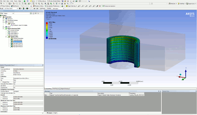
Bolted connections now give much more information, particularly when it comes to how threads perform
Since its inception, Workbench has always relied (for the most part) on the import of engineering geometry — whether using Ansys’ own DesignModeler system or a third party application (to which Ansys has many links and integrations).
While this continues (and this likely to become more so with the recent acquisition of SpaceClaim this month), the team has realised that many users also have data available (particularly mesh data) in other systems that they’d like to be able to use and reuse.
In 15.0 onwards, it’s now possible to begin a simulation process using previously created meshes, rather than pure analytic geometry from a 3D CAD system. This allows a couple of workflows to function.
The first is that it allows studies from multiple engineers or projects to be merged into a single study. Engineers can divide up work then bring this together.
The system also includes a number of tools to assist with duplication of data as well as transformation tools to ensure component meshes are in the correct position.
It also supports the reuse of data from one study in another. By allowing an engineer to import both mesh and stress data, it’s possible to have the results from one study feed directly into another — with a good example being the study of multiple stage manufacturing methods where forging or stamping is simulated, then the resultant form (with stress data intact) being used for functional testing.
The mechanism used for this is the CDB format, which can hold all the information you need (meshes, results etc.) and is widely supported, not only within Ansys’ ever expanding range of tools, but by many other simulation tools as well.
It’ll also bring across the base geometry if present and required, so that can be used to assist with selection as well as repurposing of meshes where the need arises. #
Composite design
Moving onto more specialist updates, the Ansys 15 release sees work accelerating on the composites simulation front.
For those that don’t keep abreast of the company’s acquisitions, it acquired small Swiss outfit, Even Engineering, in the middle of 2013. While Ansys has been introducing composites related tools for some time, this buy out has accelerated things.
While the last major release saw Workbench gain tools to assist with the complex business of defining how composite materials are defined in the system, this release sees that work move on and greater integration with ACP (Ansys Composite Prep/Post) for pre and post processing these types of models, from sheet material definition to ply orientation and into how the models are built from the ground up.
Alongside the greater integration in this release, the simulation of peel (or delamination) is improved over the work done in the last major update. Previous releases required that a seed crack or area of peel was defined to kick things off.
While for those investigating the cause of observed instances of this, it’s ideal, for those working on scratch built products, not so much. This allows the analyst to make a best guess, identify the plane and areas where a facture or peel is likely to occur, then have the system work from there.
Contact and bolt pre-tension
While nowhere near as specialist as composites, another area that’s seen greater intelligence added is in the definition of bolt pretension.
As those experienced with simulation will know, the ability to define a bolted connection between two or more components is beneficial, but not without its challenges.
3D CAD integrated simulation tools tend to provide the user with pre-configured tools to define the bolt, tension and influenced areas on a mesh (such as where washers and other hardware lie), but it tends to stop there.
Ansys 15 extends this type of automated tool to give you much greater control — so not only are you working with real-world values (such as thread pitch), but also pitch diameter, thread starts, thread direction (left or right handed) etc.
The results (compared to doing a complete analysis at the thread level of detail) are computed quickly and once established, can be reused wherever needed in the same model or indeed, across multiple studies. Contact modelling: Bolt pretension but also has pitch diameter and pitch distance, left/right, starts — no predefined threads — punch in the details.
Results complete much more quickly (seconds compared to an hour), which can then be reused where needed, either in the same assembly (using the sub modelling tools) or in other jobs.
Conclusion
We’ve barely scratched the surface of what’s new in this release of Ansys, but what it shows is how the company continues to consolidate and centralise its technologies on Workbench and continues to make it more intelligent.
Simulation is still a difficult process due to the complexity involved, particularly as you move into more advanced territory.
What Workbench does is get out of the way, provide a platform which enables data reuse and adds intelligence where needed.
| Product | Workbench 15 |
|---|---|
| Company name | Ansys |
| Price | on application |


