Laurence Marks discusses how you can go about modelling bolted joints in an accurate and representative manner even in quite extensive structural models
In this instalment of the Simulation Workshop we look at the humble nut and bolt. I say humble because a little while ago I was at a customer’s site and one of their team said “there are some really clever people here; some of them even understand how a nut and bolt works.”

So, there is definitely more to these things than meets the eye. If there is one aspect of analysis that has progressed in a stealthy manner over the years it’s how we handle bolted joints.
At one time you had limited scope; you either ignored the bolts, probably making that section a continuous piece of material, or, if you were working at the outer limits of what was possible, you used some short elements to connect the individual parts at the bolt positions.
This means you stressed the bolts as if they weren’t done up; and think for a minute how things behave when bolts come loose.
Even today with dirt cheap parallel computing, if the structure is large or complex it may be necessary to continue in this way. But now it’s quite feasible to model bolted joints in a more accurate and representative manner even in quite extensive structural models.

Before we get to the techniques available it’s worth looking at what we are trying to model in a little detail. So, what does a bolted joint do?
Well, it’s a way of connecting two sections of material by forcing at least two interfaces together. By forcing these faces together we can transmit a load through them, because of the friction in the interface.
Consequently, in a bolted joint that is working properly the bolts are used to pull the parts together and the loads are transmitted by the friction at the interfaces.
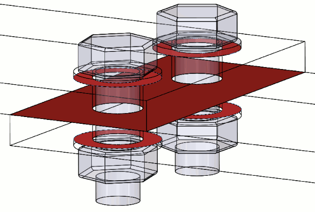
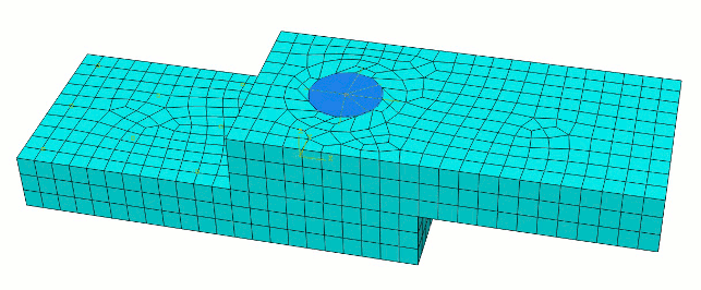
So how do you go about modelling this properly? It pretty much comes down to what your finite element system does. The techniques shown in the images come from Abaqus, and a simplified subset of these approaches are available in SolidWorks Simulation.

The basic premise of both approaches shown here is to add something to represent the bolt, and that something can be a solid mesh or a beam element. You then apply the bolt load to that. If the analysis is carried out stepwise the first step is to do the bolts up.
Subsequent steps will handle the application of load to the fully assembled assembly. The simulation doesn’t waste time modelling the faces of a screw thread moving past each other.
Doing that isn’t particularly easy anyway – I know, I tried it once. The axial load is generated by creating a set of duplicate nodes at a cross section in the bolt shank, and incrementing these past each other until the required load is achieved.
Once the bolt has been done up then there are often options that allow you to control the response to things like changes in temperature and the behaviour of the bolted components.

If you work hard enough you can even simulate what happens when you overload the whole thing.
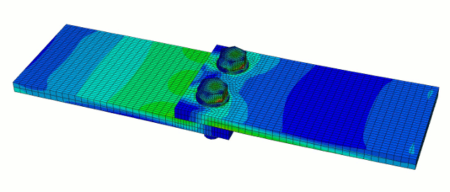
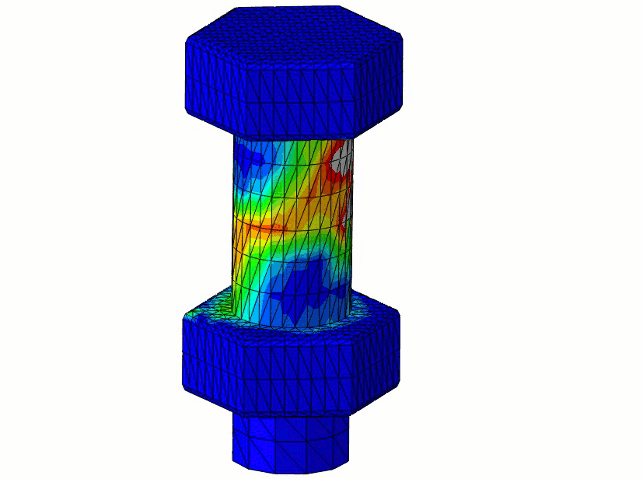
The images show a bolted lap joint which is somewhat overloaded – firstly the friction interface slips – then the bolts are suddenly put into shear with the result that they are bent out of shape.
Take the load off and you can see what damage has ensued.


