The use of simulation is growing across many sectors of the design and engineering world and the benefits are pretty clear-cut. If you can test and evaluate the performance of a product in a digital environment, without any prototyping or manufacturing costs, then you should end up with a better product. Whether that ‘better’ tag is defined as lower manufacturing costs (through a reduction in over-engineering), better performance or better quality – it should lead to increased competitive advantage.
If you read Greg Corke’s article last month on Blue Ridge’s new multi-core, cluster-aware solver code, then you’ll already be aware that the company has been doing a great deal of work to ensure users can take advantage of the latest hardware technology when conducting either thermal or fluid flow simulations of products.

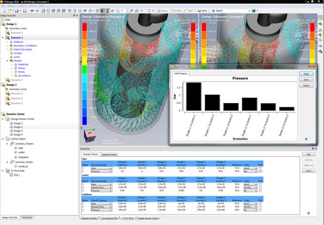
The new Decision Centre feature provides users with an environment for the assimilation and comparison of results from multiple scenarios, using summary tables, graphs and plots
The 2010 release brings a host of tools for those looking to make the most of their time when simulating fluid flow and heat transfer. Perhaps the biggest shift for this release is the ability to conduct multiple design studies within the same interface and within the same dataset. While previous releases have facilitated multiple design studies, this release brings this to the fore and gets rid of the workarounds. This is done on two levels, both when setting up those studies, and then when providing the tools to visual and interrogate the multiple results sets.
Multiple studies
Everything that pertains to a design project can be stored in a single dataset and this means multiple studies can be carried out within the same working environment.
To define a study the first stage is to set up the geometry. CFdesign has always had rock solid connections to the majority of CAD systems, either through native data transfer or through standard/proprietary formats (such as ACIS or Parasolid). Once the geometry transfer is complete, the details required for CFD need to be added.
For an internal flow problem (such as a valve or pump) the inlets and outlets need to be capped off, which is a trivial matter within CFdesign. For an external flow or a product simulation, which has both internal and external flow or transfer, then the volume within which it operates needs to be defined.
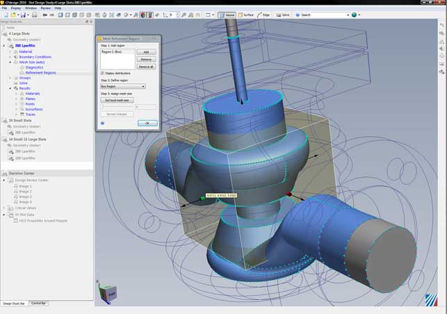
CFdesign 2010 has new direct modelling type techniques for quick, efficient modelling of external volumes. Geometry can be pushed and pulled into shape, and basic primitives are used to build up the required form. Incidentally, the same tools are used to create regions for mesh refinement later on in the process, allowing users to zero in on areas where more accurate results are required.
Dynamic input has been increased across the board, with the system feeling much more interactive when working work with the model, rather than pulldowns and dialogs.
The next stage is to define the inputs and outputs, fluid regions, heat sources and then the simulation can be run. This is pretty much unchanged from the previous releases in terms of workflow, but has become much more interactive, focussing on the model and context sensitivity input.
The dramatic change for 2010 is that much of the work from the first study can be re-used to carry out further investigations. Reusing a project is pretty simple. Assuming that the same geometry is to be used, the project is simply cloned. This creates a copy of the original and another branch in the simulation tree – or as it’s known, the Design Study Bar. From here the inputs can be adapted as required and the analysis re-run.
If different geometry is required, perhaps swapping potential design variants or family members, then users have full control over individual parts and sub-assemblies as well as part suppression tools.
Results interpretation
Once one or more results sets have been created, and assuming the results are accurate, the important stage of the process begins, that of results interpretation. The Decision Centre provides a centralised set of tools for inspecting multiple results sets. Up to four datasets can be loaded up at one time and these can be displayed in a very organised manner. Views are synchronised, so it’s possible to dive into each and find weak points, inspect areas of concern, and have the display in other datasets maintain the same view.

CFdesign 2010 features a set of direct modelling tools that allow you to create external flow volumes using primitives quickly and easily
The results data is presented in a tabular manner, so multiple sets of data can be filtered down to find those of most interest, and those which need further investigation, without any impediment. Charting and graphing tools are also supported in this environment. While the fancy 3D fringe plots are fine for getting an understanding, it’s these more traditional types of output that will be used as the basis for design decisions.
Alongside this, there is the full array of result visualisation tools that CFdesign has had for some time, for vector plots, flow animation, and iso-plane creation. These too have been enhanced. For example, textures can now be placed on components to help add context, the existing cut-planes can be formalised in the Study Bar, so they can be used across multiple studies when projects are cloned (rather than having to create them individually). Finally, a reference value can be added when plotting charts, whether that’s a performance metric, or a pass/fail benchmark. At present results can’t be colour coded on the basis of that reference but it’s usable all the same.
The importance of CFD
Simulation is a rapidly advancing field with many active vendors. Some are more traditional, providing the higher-end, PhD driven systems of old, while others are pushing simulation and analysis into the mainstream, providing tools that designers and engineers can dig their teeth into. Of course, whichever system is used, having a solid understanding of the principles behind these systems and physics they describe, is key to getting good results.
The main advantage of any simulation tool is to prove out a design variant before it moves to physical prototype or manufacture. But doing a single simulation doesn’t give you much – it just gives you a binary answer (yes or no/ pass or fail). To make full use of these tools, you need to be able to explore a design, to play with values, variables and inputs and see what the optimum solution is within the defined constraints.
Conclusion
This release of CFdesign is impressive. Having watched the application grow over the last ten years, it’s rapidly gained a position as one of the leading examples of truly designer-led CFD. CFdesign 2010 is not about flashy new functionality, it’s about taking the existing tools and making the most of that functionality.

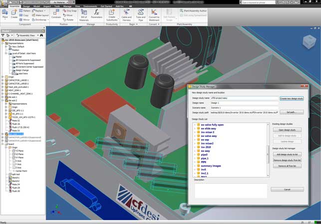
The Design Study Manager allows users to quickly and easily create and manage multiple designs and scenarios from any MCAD environment, such as Inventor
From the tools that manage the movement of data from your workhorse 3D CAD system to CFdesign, through the revamped working environment (which is rather elegant in its simplicity) and then onto the new Decision Centre’s visualisation and reporting tools, this release is all about enabling the user to make real and high-impact design and engineering decisions, based on digital experimentation, and not just a cursory peep in a product’s performance.
The ability to visualise and inspect multiple data sets in a single window, without having to load multiple files, or manage multiple graphics displays, sounds like a small thing, but the power it gives you to see trends, finds weak spots, tweak performance, is incredibly compelling. All in all, it’s a good release and I can’t wait to see what the team comes up with next.
| Product | CFdesign 2010 |
|---|---|
| Company name | Blue Ridge Numerics |
| Price | Price on application |


