
nTop Platform 2.4 – The geometry that designers and engineers are asked to create is increasing in complexity, as companies explore new ways to manufacture products. We look at a tool specifically built to make lighter work of such projects
If you’ve been following the design and engineering software industry over the last few years, chances are that you’ll have come across a New York-based start-up called nTopology.
Founded in 2013 by Bradley Rothenberg, nTopology has gained a reputation for developing advanced software that looks to solve some of the most challenging, geometric-led design challenges we face.
nTopology’s bold mission statement boasts of its intention to build “the next generation of engineering design tools for advanced manufacturing.”
In even a cursory trip to the company’s website, you’ll spot a lot of the kinds of forms that now get attributed to ‘advanced manufacturing’; these included generatively optimised forms, lattices and more.
What’s harder to track down is a clear, concise explanation of what nTopology’s nTop Platform actually does.
So that’s our goal here: To temporarily set aside talk of ‘future this’ and ‘advanced that’, and dig down into what the bloody thing can actually help you achieve and how it goes about it. Ready? Let’s go.
Familiar workflows versus new methods
Once you’ve got nTop Platform set up and licensed, you’ll fire it up and be greeted with an interface that follows pretty standard lines.
There’s a large 3D modelling window, a strip of toolbars across the top, pull-down menus above that and a panel to your left.
If you inspect those toolbars more closely, you’ll start to see that once you move beyond the immediately familiar (primitive geometry shapes, basic sketching tools and modelling operations such as extrude, sweep and so on), you begin to find some surprises that suggest that things are a little different in nTopology’s world.
Here, we are not talking about modelling functions and feature creation, but rather, tasks associated with the creation of more complex forms: surface treatments and meshing; stress analyses from which to derive optimisation results; all the lattices you could ever need.
But before we get into the meat of the system, let’s explore how you start to build up a workflow.
Central to this is blocks. The concept is straightforward enough.
Whether you create your geometry from scratch using primitives, features and Booleans, or by importing CAD geometry, you will need to start off by adding some blocks to the ‘Notebook’ found to the left of the user interface. These blocks are the central method for creating your models.
Where traditional 3D modelling systems use predominantly geometry-based, linked steps in the form of a history tree, nTopology’s approach differs.
Essentially, each block you add to your notebook describes an operation or function you want to perform.
You then link to the various parts to which you want to apply those operations.
Where traditional modelling systems immediately create a set of heavy geometry, nTop delays the creation of ‘hard geometry’ until you actually need it. Everything works on the lightest set of data possible.
For example, if you want to take a geometric form and create a lattice from it, you might start with a block that imports your geometry from a CAD file (for example, a Parasolid or ACIS file).
You then add another block to convert that CAD geometry to an nTop body. To do this, you add ‘nTop Body from CAD’, then either drag and drop your CAD import block, or type in the block name.
This creates the link between the two steps and the system processes it.
Then, if you want to create a volume lattice from that nTop body, you find the Volume Lattice block, link it to your nTop Body block and add in the required parameters (such as lattice type, orientation, sizing and so on). Hey presto, you’ve got a parametrically driven lattice that conforms to your CAD geometry.
What’s important to note here is that doing this using a traditional CAD system would effectively kill your workstation.
Why? Because traditional CAD systems need to create the complete geometric definition and display it, which typically requires a tessellated version of that lattice under the hood. By contrast, nTop doesn’t.
Instead, it keeps things lightweight until you need to convert to a mesh or export your data.
Efficiency benefits aside, this may sound an awful lot like a history tree in a traditional CAD system – and in many respects, there are close similarities.
What differs here, however, is that the blocks and processes you build up are much less reliant on underlying geometry.
As an example, if we took a short, three-or four-step workflow, imported another CAD file (of completely different geometry), and relinked the initial nTop body block to that new CAD import, you’d see the system quickly work through and carry out all of the subsequent operations on that new form.
Yes, this is a very basic example. Yes, as you create more dependencies (such as specific faces or other geometry references), there is more work required to reapply operations to new geometry.
But either way, the robustness is there for users to take advantage of.
nTop as a design system
So now that we’ve got a handle on the basics, what can you do with nTop?
For a start, it has some interesting modelling tools. Whereas other mainstream systems rely on explicit operations and logical history, with nTop, things are, again, a little different.
Take the example of combining two or more geometric entities into a single body and then smoothing the transition between the two.
In a traditional system, that would require two operations: the first to create the geometry; the second to create a filleted transition between the two, which might work or might not, depending on your requirements.
In nTop, this is all part of the Boolean process, so you have control over the form of that transition area from the start.
You can have that transition as a rounded fillet, a chamfer, a blend, all to the radii you want. That means there’s less selection work required, and more automation and control.
Between simple forms, this may not seem that different to how things work in other systems – but now consider a complex lattice inside a more traditional geometry.
It’s good practice to have a small fillet at the junction point, for both strength and heat dissipation during build.
Adding a fillet between a lattice and its surrounding geometry using a traditional modelling system would be an epic task and one with a very high risk of failure.
With nTop, it’s performed automatically. One thing that is key to understand is that different operations require different inputs in nTop.
For example, while you can take an nTop body and create a volume lattice, if you want to create a surface lattice (perhaps to build up some ribs that better suit the stress profile), then you’ll need to create a mesh onto which this surface lattice can be built.
It takes some time for newcomers to the system to figure out these intricacies, and while the help system and in-window assistance are both useful, nothing will get you up to speed quicker than diving in and learning the system from the ground up.
One concept that I found particularly complex to learn was that of field-driven design of geometry.
To break this down, nTop allows you to take a set of geometry and create the form you need from it, using geometric references and standard dimensions.
You take a surface, create a lattice across it and then thicken that up, according to a numerical value. That has real value and real benefits.
Where things get interesting is when you start to use simulation studies to add more control over those forms – such as using the stress fields from a simulation study to control how thick lattice beams are across a part, for example, or using an imported pressure map to drive the thickness of a set of ribs around the exterior surface of a pressure vessel.
If you want to get the most out of nTop, then you need to get your head around fields and how to use simulation results to drive geometric forms, either using the built-in stress, strain and modal analysis tools or importing results from other systems.
Toolkits are key
While the tools we’ve discussed represent the basics of the system, it can be a daunting process to jump in and start building up your own workflows.
To assist with this, nTopology has introduced Toolkits – collections of pre-baked workflow elements that give you more usable functions straight out of the box.
There are currently five digital toolkits available.
These cover: Additive Manufacturing, Architected Materials, Lightweighting, Design Analysis and Topology Optimisation.
Each toolkit brings together the various parts of the system relevant to the specific workflows and tasks in question, as well as adding in new blocks that define a specific workflow.
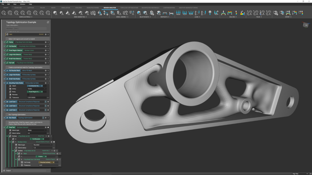
For example, within the Topology Optimisation toolkit, there is a workflow for carrying out a single-body topology optimisation, complete with clear guidance on how to perform the task.
Once done, you can use the results to create smoothed-out forms (again, there’s a workflow within the toolkit) for integration with other geometric features to create the final part.

Manufacturing integration
As you’ll have gathered, there are some serious issues surrounding the creation of complex geometries, particularly when it comes to latticed forms.
The pure amount of geometry required to define some forms means that the process of preparing data ready for manufacture can be problematic.
This is particularly true when you’re dealing with additive manufacturing machines.
To assist with this, nTop Platform offers a set of tools that will assist not only in preparing data for additive manufacture, but also in directly communicating with machines to ensure that your design intent is maintained throughout the process.
From the first instance of readily importable build volumes, the system manages build layout and support generation and handles tasks relating to slicing and machine specific data creation.
In conclusion
I’ve been talking to folks curious about nTop for a while. After all, we’re all interested in new ways of defining parts, both for function as well as form, just as we’re also keen on exploring new forms of manufacture and production.
While nTop has been associated with advances in additive manufacturing, to think of it as an additive-specific software product would be an error.
There’s huge scope for the system to benefit more traditional design and engineering.
Consider the design of conformal ribs to complex shapes, for example; that’s something that can take hours of work, if not days, using traditional tools.
Then consider that much of that work would need to be redone in the event of any design change.
Unless you’ve got robust modelling practices, you’re looking down the barrel end of a whole load of rework.
By contrast, nTop allows you to define a set of operations and activities that can be very quickly taken and reapplied to new geometric references.
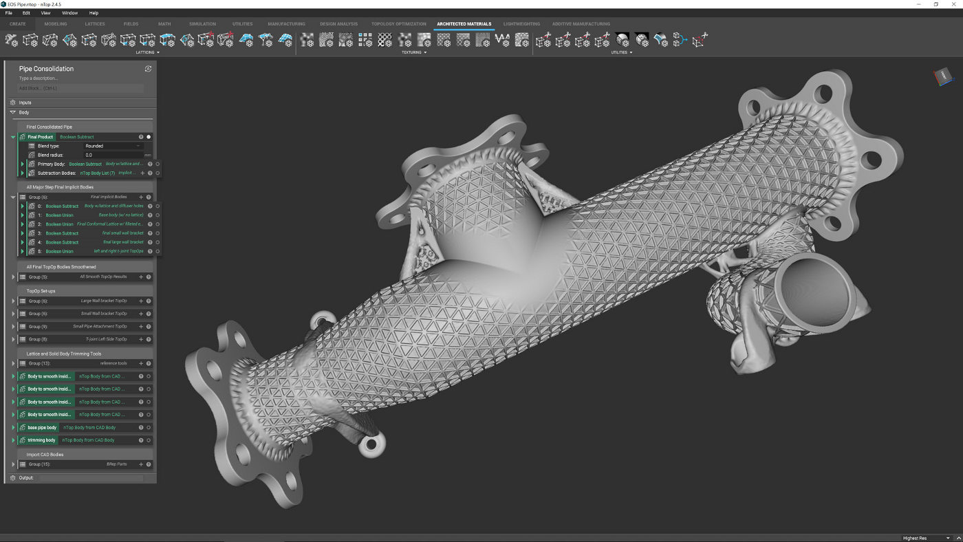
If you take a look at Figure 3 (above), you’ll see a set of operations that create those fundamental lattice structures; we developed these using a basic set of geometry and made sure they were robust to change and modification.
Now, this can be applied to any input geometry that vaguely has the same requirements. A common question I’ve been asked about this software is, “Will this replace my existing CAD system?”
The answer is no, absolutely not – unless you’re doing some very specific work and, even then, it’s likely you’ll still require a more traditional modelling tool to define your design space and domains.
While nTop features modelling tools, those with years of experience with traditional 3D CAD will find it quicker and perhaps more sensible (in terms of workflow and data compatibility) to do that work in those systems, and then pass across the data you need for further, more complex work in nTop Platform.
As it stands, nTop Platform is a supremely impressive set of tools for those interested in complex part and material design.
We’re entering into an age where we have more freedom of geometry for parts, both at the part scale and material level.
Whether we want to directly produce hyper-optimised forms to save weight and energy, or incorporate materials so that function is built into the part at mesoscale, we’re going to need a different class of design and engineering tool to achieve such goals.
Our current 3D design and engineering systems, frankly, are fundamentally unsuited to defining and/or effectively representing these types of forms.
You’ll notice that we’ve not gone too heavy on the specifics of what nTop Platform does, and with good reason.
When looking at a system like this, it’s too easy to make assumptions based on what you already know, and I don’t want to turn people off by talking about specifics, when it would be better to encourage those who are curious about all this to get hold of a trial of the software and simply experiment with it.
After all, it’s built for experimentation and exploration of function, form and production methods.
All of the building blocks you need to achieve incredible things are there and the nTopology team has prebaked some very useful workflows on top of this platform to help you on your way.
If I had one criticism, it’s that there are no concrete, quotable details from nTopology on how much the system costs.
We’ve seen indications elsewhere that it’s around the $7,500 per user, per year mark, which seems high and depends on number of seats and company size (which is disappointing).
The company has something really impressive on its hands here. I’d hate to see this product not get the attention it deserves due to pricing issues.
But if nTopology’s leadership team can nail down the prices, make them transparent and discuss them publicly, then nTop Platform stands a better chance of success in a marketplace full of would-be buyers who are crying out for a system like this.
Workflow: Getting your first part built in nTop
There are not many systems like nTop around.
It’s built for experimentation, rather than documentation of design and engineering and, as a result, the skillset you already have from CAD use will only get you so far.
The good news is that once you’ve got your head around how it works, how to connect up blocks and carry out functions, the sky really is the limit.
To learn more, we went through the tutorials and then dived into working out how to define the shapes and forms found in existing products. One example that proved worthwhile from a learning perspective was replicating an Acetabular Cup used in hip replacements.
This features traditional forms combined with lattice forms and is designed to assist with osseointegration (where bone grows and integrates with an implant).
Learning the process required us to define a lattice that both connects to solid forms and fits within the design space, which proved a worthwhile exercise.
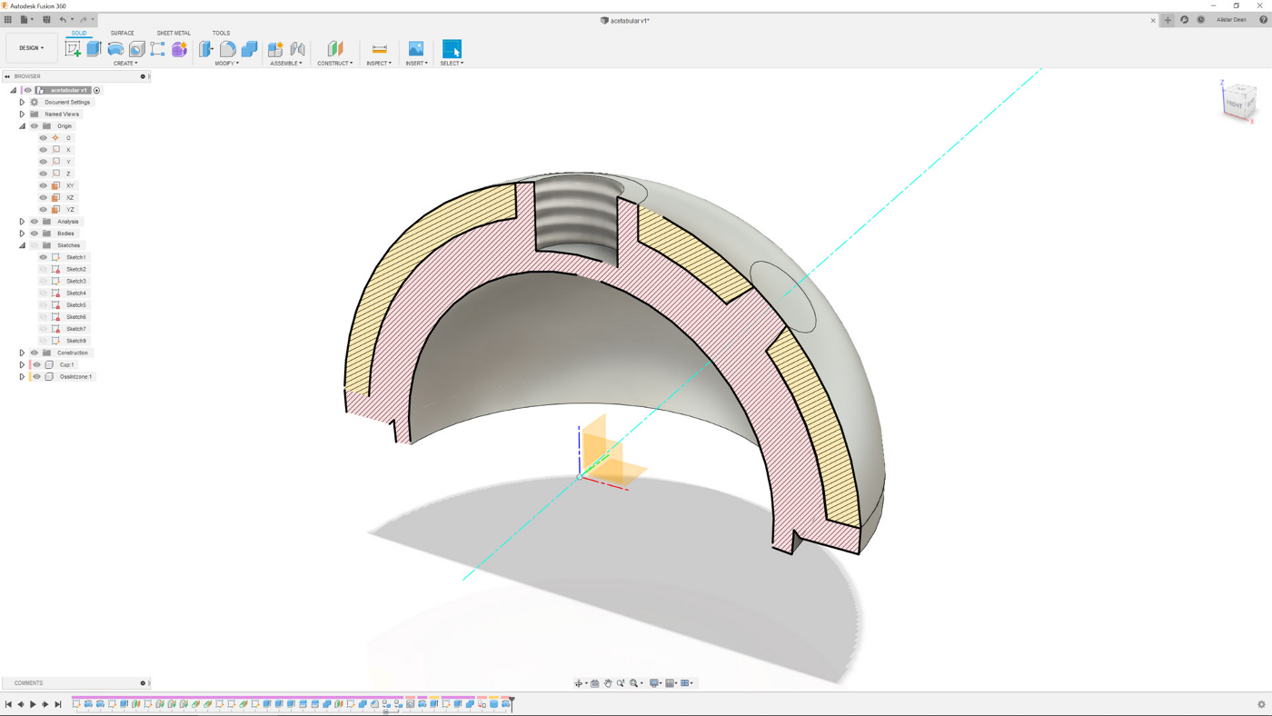
●1 Let’s work through the basic steps of developing a 3D latticed Acetabular cup – a pretty common medical implant these days. It features mechanical fixturing points as well as latticed structures that assist with bone integration. We’ll start with a rough CAD model created in Fusion 360.

●2 Within nTop, you add ‘blocks’ to the notebook on the left-hand side. To begin our project, we use ‘Import CAD geometry block’, point it to an exported SAT file and give it a resolution (leave it coarse for now). You’ll see that this is a yellow block, indicating that it’s an input.
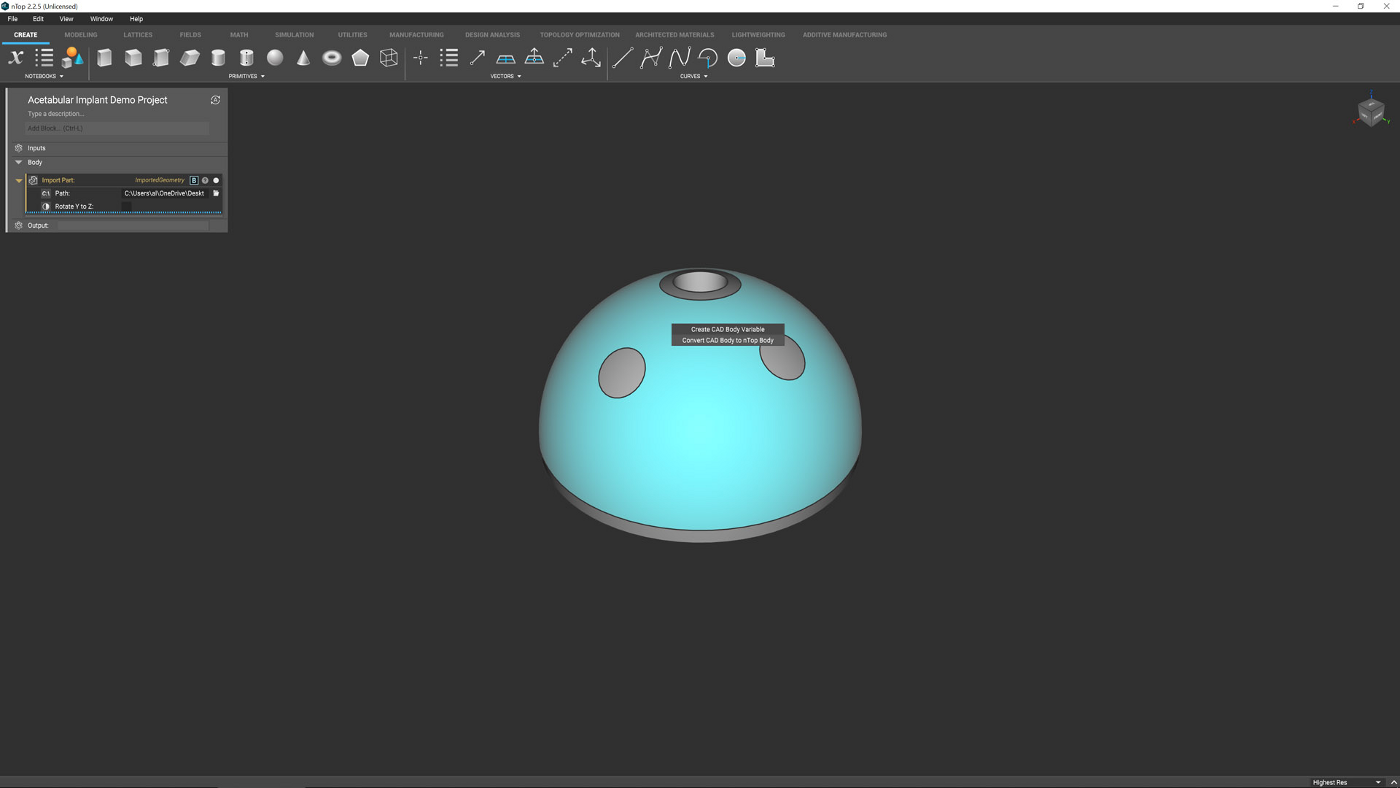
●3 The next step is to create ‘nTop bodies’, giving you a more appropriate dataset to work with. For this, we have created two nTop Bodies: one for the main body of the implant and another for the zone to be latticed up. Name these well – it makes maintaining references much easier.
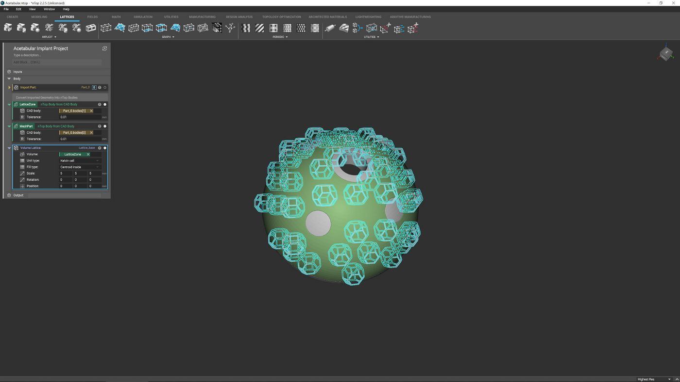
●4 Now let’s start building up a lattice. Select the Volume Lattice from the toolbars (or use the quick search option) and connect it to your lattice-zone nTop body. Ensure you have the ‘touching’ option selected, otherwise (as you can see here), you’ll end up with only a partially fitted lattice.
●5 Once the options are about right, you can begin to experiment with lattice forms. Look for what feels right or, as in this case, which lattices gives you the correct form to serve the function required (such as greater bone integration). Remember that this is a lightweight version of your form.
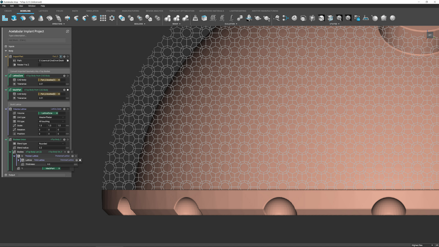
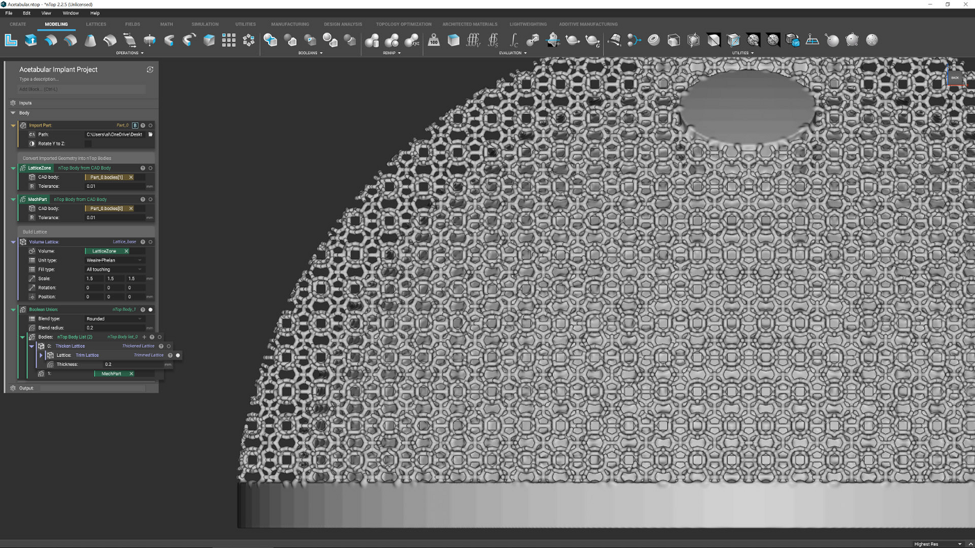
●6 To take a true look at your lattice, you need to add thickness to the beams. There’s a wide range of tools to do this (based on FEA results, distance from other parts and more), but in this instance, a simple thickness value is given to the Thicken Lattice block.
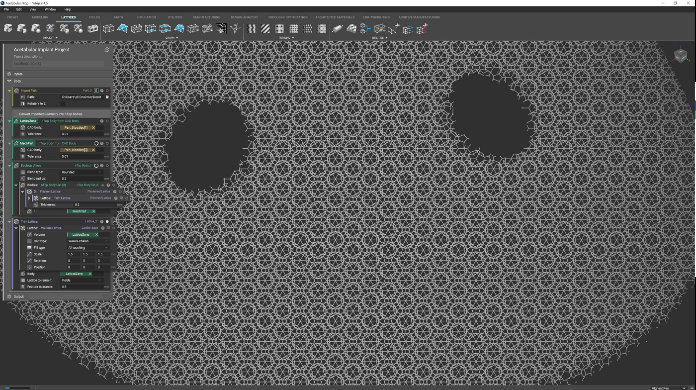
●7 Your basic lattice layout is now in place, so you can use a range of tools to further refine it. There are tools available to remove or extend open beams (useful for ensuring better connectivity to surround geometry) as well as trimming it to a solid body (as we’ve done here).
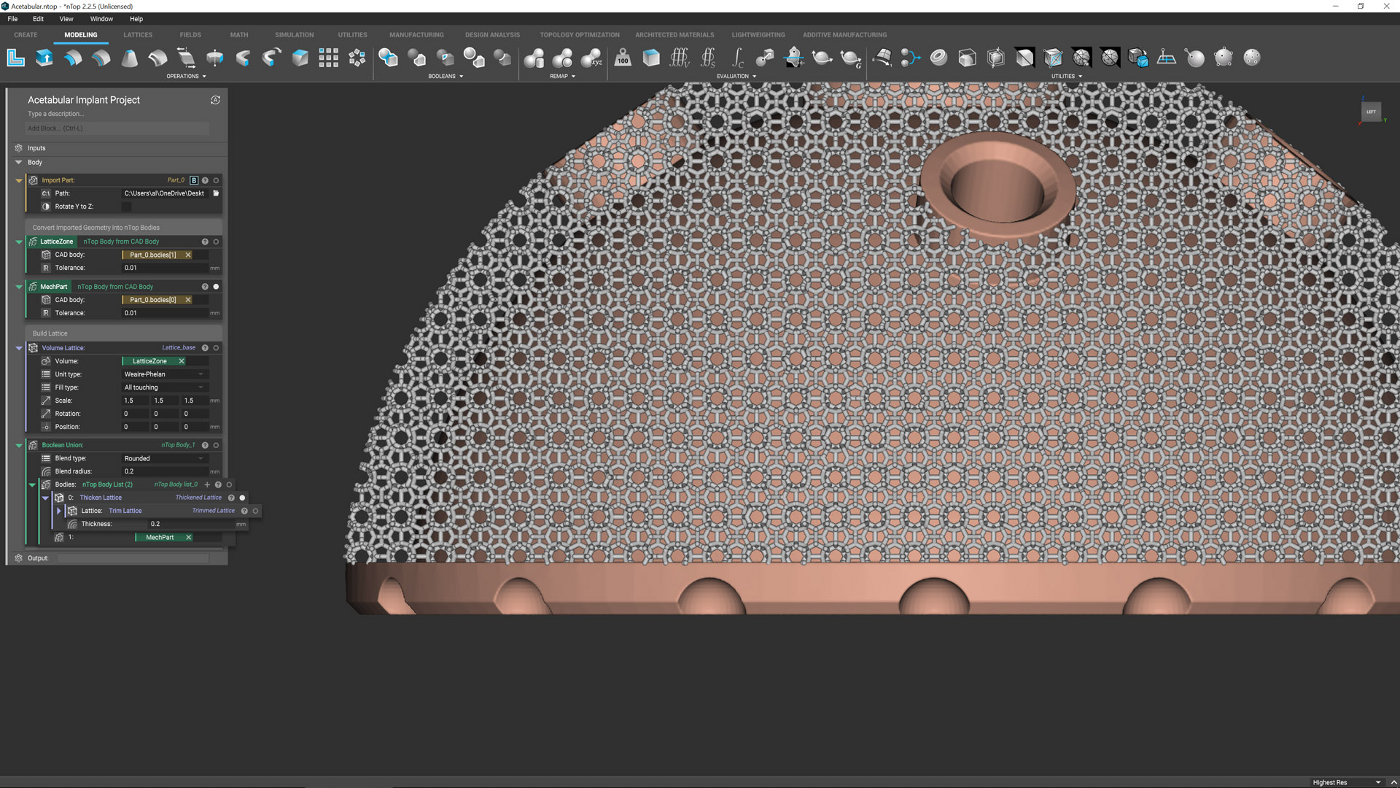
●8 Now, you have the central geometry section, then the geometry of the lattice. The two intersect, but are not connected. To achieve a cohesive whole, you need to carry out a Boolean union between the various bodies. nTop has a range of Booleans, something you don’t see in other tools.
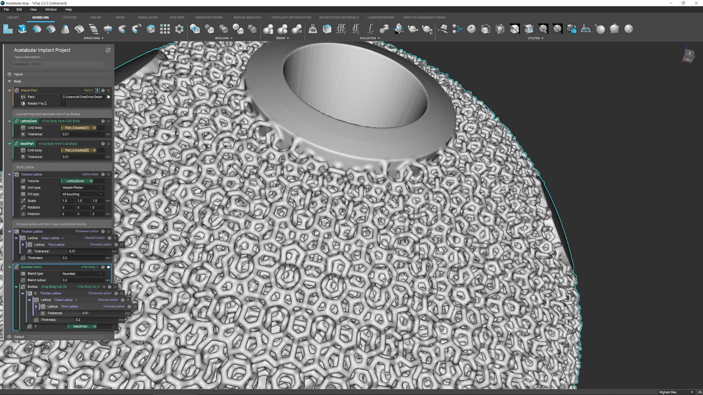
●9 Boolean operations in nTop are impressive. They allow you not only to process geometry in respect to each other, but also manage how transition areas are handled. For example, there are controls over how the lattice joins the central part of this form, in terms of both shape and size.

●10 As with all good design projects, we have a design change that needs to be accommodated; in our case, we’ve developed a more featured version of the base geometry in Fusion and exported a V2 SAT file. In other systems, this would mean reworking the whole process.
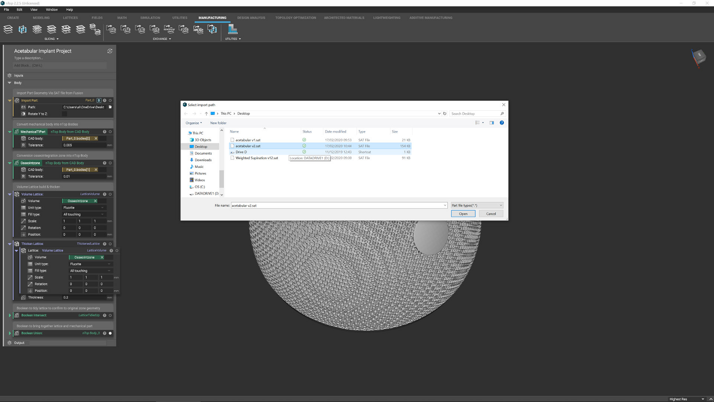
●11 Since nTop is built on a series of interlinked blocks, rather than an explicit set of geometry operations, it’s a little more robust for handling wholesale design changes like this. To start the update, you edit your initial ‘CAD import’ block from Step 2 and point it to your new SAT file.
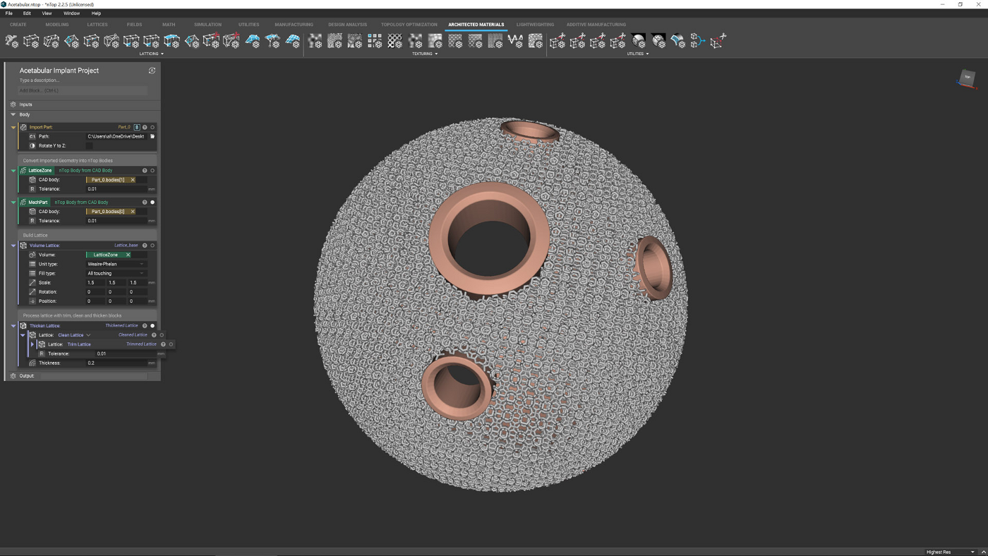
●12 The system then works through each stage where possible and recomputes everything. As this is based on the same geometry set, unchanged topology references should transfer, but if they don’t, it’s a simple case of reassigning broken links – saving you a lot of time.


