
Geomagic Design X – The combination of technology acquired by 3D Systems from Rapidform and Geomagic really shows up in the latest update to the company’s Design X software for fixing-up scan data for use in your design and engineering workflows
Geomagic Design X is a product with a somewhat complicated back story. Developed by 3D Systems, better known for its 3D printers and on-demand manufacturing services, the software has its roots in two acquisitions made by the company some years ago.
The first of these was 3D Systems’ 2012 purchase of the Rapidform product line-up from Inus Technology, which focused on tools for post-processing 3D scan data into analytical surface models and for scanbased inspections.
The second acquisition, of Geomagic, took place the following year. Again, the focus here was 3D scan data post-processing and scan-based inspections.
There was some sense to this: at that time, 3D Systems was also developing 3D scanner products. But in effect, the company had purchased two arch-rivals and two sets of very similar functions, albeit with their own slightly different approaches, different user interfaces and different underlying technologies.
Since then, of course, there has been consolidation. 3D Systems has settled on a single platform, named it Geomagic Design X and combined the best capabilities from the Rapidform and Geomagic stables to create three separate products.
First, there’s Geomagic Control X, covering inspections based on scanner data, as well as that captured by other devices, including arms and coordinate measuring machines, or CMMs.
Second, there’s Geomagic Wrap, focusing on improving scan data, and in particular, integration with various 3D printing platforms.
Finally, there’s Geomagic Design X, the focus of this review. This is intended for fixing scan data and for creating analytic surfaces that will feed more readily into your 3D design system for downstream use.
Geomagic Design X – user interface and workflow
The Geomagic Design X user interface should look pretty familiar. You’ll find a ribbon of icons across the top, categorised by task: Points, Polygons, Regions, Alignment, Sketch, Exact Surfacing.
There’s a model tree on the left-hand side, containing a list of all of the data you create, from points and polys to surfaces and sketches.
As you’ll see, the large modelling window also contains context-sensitive menus that guide you through the various commands and operations. Luckily, this type of tool has a pretty linear workflow.
You start with your point data, which can be imported from a number of systems and in different formats. Geomagic Design X also offers the option to connect to scanners directly and stream the points directly into the interface.
Either way, once you have points, you need to process them. Geomagic Design X combines expertise from two leading organisations in just this kind of work, so you have everything you need to filter, streamline and clean up those points.
Outliers can be dealt with quickly; unwanted sections of scan can be removed rapidly. With that work complete, it’s probably wise to decimate the resulting point cloud to some extent.
Although Geomagic Design X is built to handle large quantities of data, reducing your point cloud by removing extraneous data will make your workflow more efficient.
Next up, you need to create a polygon mesh. (In some situations, of course, you may already be starting with tessellated data.) Geomagic Design X offers a wealth of tools to help you repair your polygons, with the goal of achieving a mesh that is smooth where needed, but also has sharp edges where these are required.
Along the way, you’ll be running automated healing and repair routines, removing scan markers and eliminating features that you don’t need.
Now that you have a set of polygon geometry that accurately represents the form that you’re looking to reverseengineer, it’s time to plan out how you’re going to do that.
Polys to surfaces
There are a couple of approaches to taking your polygon mesh and turning it into proper surfaces and solids. One approach is to use the surface patching tools and to select regions of your model to turn into freeform surface paths.
There are a number of tools to accomplish this, based on both automated processes and more manual input. This is where the product’s mastery of surface wrapping comes into play.
The other method is to break down your object into primitives and start to model it up using a combination of extracted references, curves, sketches, features and primitives.
This is where the power of Geomagic Design X really becomes apparent. Looking at the ‘Model’ toolbar, you’ll see that you have a wide range of sketching, feature modelling and operations to help you.
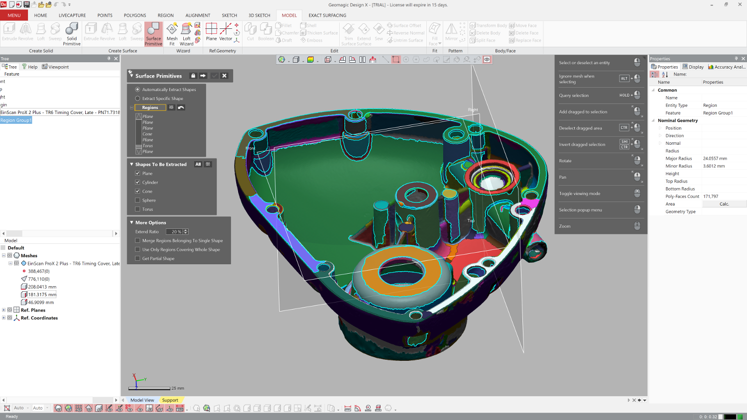
A good starting point is the Region commands: these analyse your model and find areas where there are clear breaks in curvature (based on user-defined values). This will help you to identify areas such as planar faces, cylinders, cones, torii and more. From here, you can then start to work out how to rebuild and reverse-engineer your form.
If you need to create sketches, there are interesting tools available to do this. Imagine, for example, that you want to build a sketch from the part in Figure 1 (above): you would need to select the planar region where the sketch is, then use an intersection curve.
Of course, scan data never works this precisely, so it might be better to offset where the section is taken from. Mesh Sketch lets you do that within the command, offset into the part and project back to where you want it.
Smart readers will notice that there’s a draft, so your projected sketch entities will be slightly off. The good news is that there’s a draft option in the Mesh Sketch command that helps you to account for this. It’s also worth noting that the system does an incredible job of translating the often ‘noisy’ sections created, giving you a decent sketch that doesn’t take too long to repurpose when you need to build features.
The goal here is to use the wealth of tools in Geomagic Design X to build up your model, pulling references from your scan and mixing and matching them with measured and idealised dimensions – just as you would with a traditional history-based modelling workflow.
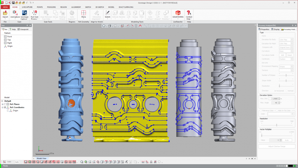
At any point, you can switch on the Accuracy Analyzer, which will show you how far you’ve got and to what extent you’re deviating from your scan.
Of course, it might be the case that you want to mix and match approaches. Our favourite test part offers a combination of both organic surfaces, which are best wrapped, and more analytic features, based on primitives.
Other projects might simply require a couple of surfaces pulled off the mesh and transferred to your CAD system. It’s also worth noting that, in many instances, it might not be necessary to scan the entire part. Take the example of an alloy: since it repeats, you’d only need to scan a portion of it, model up that segment, and then use the traditional arraying tools to build out the final part.
Updates in Geomagic Design X 2021
There have been a couple of updates to the most recent release (2021) of Geomagic Design X that are really worth highlighting.
One is selective surfacing. As we’ve already discussed, using regions in Design X makes easy work of turning complex, freeform shapes into a surface model, but it’s often the case that you want to skip a feature that’s part of the scan.
One possible workflow is to delete those portions, patch them and create your surfaces. The issue there is that you might need those areas later on. Selective surfacing allows you to define which areas to surface and which to ignore.
This will automatically skip the ones to ignore and patch your surface to the areas you’ve selected, resulting in a single set of data to work with and a more efficient reverse-engineering process.
It also allows for a faster hybrid modelling approach, which combines automatically generated surfaces (through selective surfacing) and traditionally created parametric modelling features.
Another is the ability to quickly separate a mesh into its constituent parts. This means you can scan an assembly in a project and then use the system to quickly split out different chunks to work on individually.
This tool also allows you to quickly decouple background objects or portions of 3D scans that you would like to delete. This is a nice example of how the operations in other parts of the company’s portfolio feed into each other.
The last new feature I want to cover is the Unroll/Reroll feature, which is one of the most interesting I’ve seen for some time in any chunk of software.
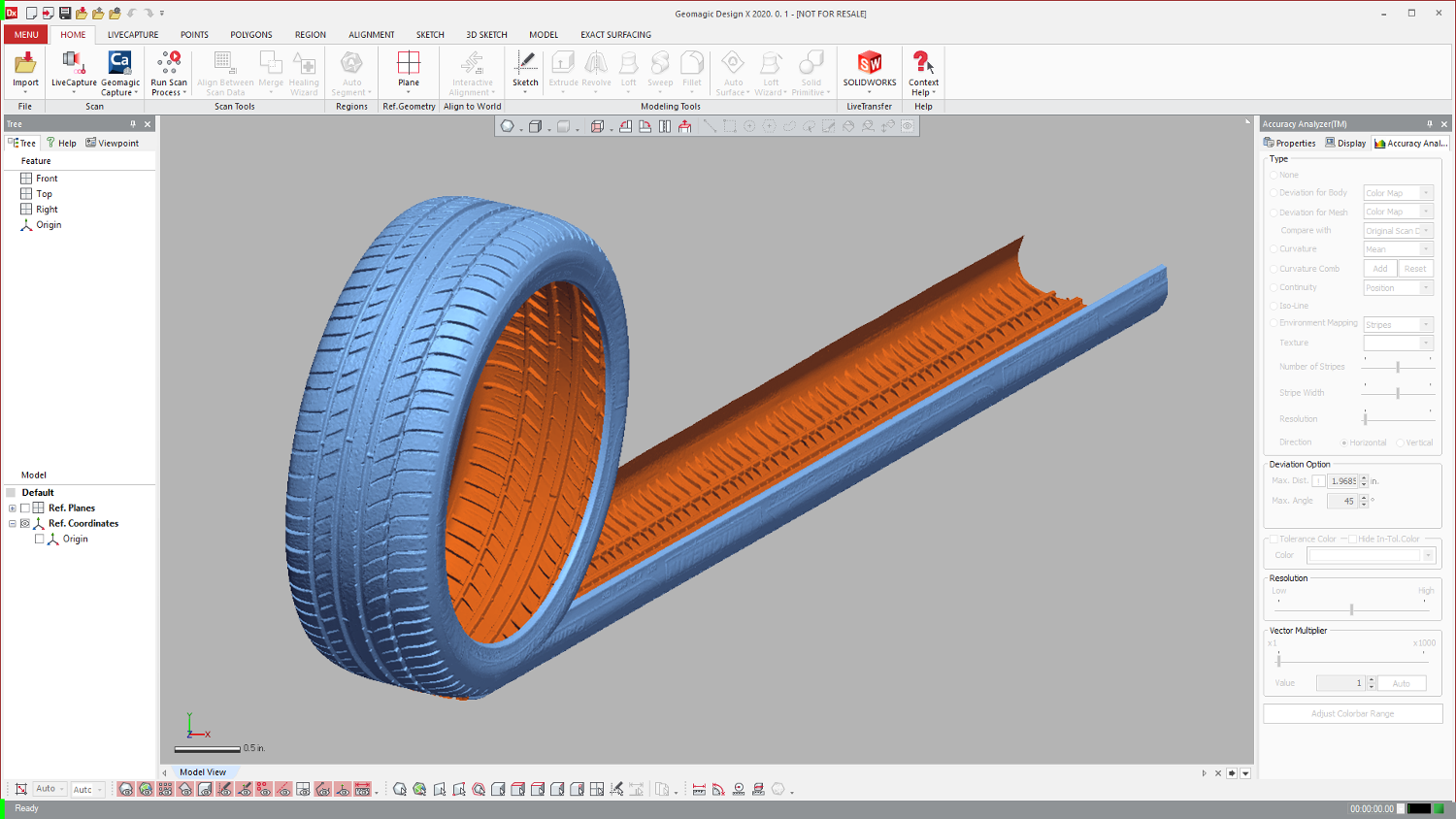
Imagine, if you will, a scan of a cylindrical object with a pattern or form that is cut into or out of that form. It might be a tyre; it might be a complex cam; it might be an ornamental object.
Now, imagine the nature of that data as points and subsequently polygons. As a last step, imagine unrolling that object so that the base material shifts from cylindrical to planar, taking with it all of the details. This is what the Unroll/Reroll feature does.
While there are tools available in traditional CAD systems that might do this, this is the first time that I’ve seen this accomplished with mesh-based data.
You simply select your mesh and define an axis around which to unroll. Then you need to define a starting point for that unroll.
This can be a plane, a sketch, whatever. The thing to consider is if you were flattening out a cardboard tube, you’d need to split it. It’s the same with software. Once done, you’ll find your mesh nicely unrolled and flattened out, retaining those details you need.
This approach can be taken even further, since the designer now has the power to work in 2D space to accurately define a cylindrical object, and additionally reroll that precise sketch back into cylindrical space. In this way, they can achieve precision reverse-engineering of rotating or cylindrical parts.
Geomagic Design X – exporting your data
The end result is, hopefully, a geometric model that represents the data you have scanned, processed in a manner appropriate to your requirements. If you’re looking to scan an existing component that’s been damaged or worn, then you’ll be looking to remodel it to its perfect state.
Alternatively, if you’re looking to replicate an as-found physical object, you’ll take a different approach. Similarly, when exporting that data, the approach you take will differ depending on your needs.
Geometric data can, of course, be exported as a STEP, IGES, Parasolid or ACIS. The system also includes Catia V4 and V5 support.
But alongside this, Geomagic Design X has another trick up its sleeve, which will be of great use to those looking to take reverse-engineered data into their workhorse CAD systems. As it has captured the modelling process, Geomagic Design X can dynamically rebuild the same data in Solidworks, NX, Creo, AutoCAD, Inventor or Solid Edge using the Live Transfer operations.
Live Transfer is a direct link into your CAD system of choice, and supports automated, feature-by-feature rebuild of your model, so the end result is as if it was modeled natively, highly and direct directly reusable.
In conclusion
I’ve not looked at the updates made to this system for quite some time and it is clear that 3D Systems has done some incredible work on it over the intervening period.
The combination of Rapidform and 3D Systems’ knowledge and capability shows up in all aspects of using Design X – from being able to connect directly to your scan hardware, to carrying out your point and poly mesh processing, through to the incredible tools for reverse-engineering those forms in the manner most appropriate to your project.
Whether you’re looking to scan a physical object in order to pull some reference surfaces for a new part or subassembly (think aftermarket car parts and such); or capture a part and represent it using organic but analytic surface models; or indeed, fully remodel a part as a parametric model, it’s all here in Geomagic Design X and ready to use.
I would imagine that most projects that readers will undertake will demand a mix of each approach – but the good news is that you’re not jumping from system to system to accomplish this and can instead stay focused on the process. Outstanding stuff.


