
Vericut 8.1 – Simulation is a standard part of CNC machine programming but if you’re looking to truly verify your G-code, a system separate from your CAM system is the only bulletproof way to do it. We look at just such a system
If you’ve developed G-code to run on a CNC machine (whether that’s a lathe, a mill or something more exotic) at any point in the last 30 years, the chances are that you’ve come across simulation has part of that process. With CAM simulation, the CAM system uses a combination of the cutter geometry, movement of that cutter through your material, knowledge of your stock model and some clever tricks to give you a representation of your final part.

Vericut allows you to simulate and verify everything that influences the quality of your part
So how does CNC verification differ from the more familiar CAM simulation? The answer lies in the simple fact that while CAM software vendors make the greatest effort to ensure their CAM operations are error free, the fact that you’re using the same system to simulate the code means that any errors anywhere in the whole process, won’t show up until you start cutting metal.
This is where verification steps into the process. By separating the process, using an independent set of tools, it’s possible to model the complete system. A verification system allows you to sanity check every operation, every movement of the cutting head within the confines of your machine and ensure that it works as described and as needed.
This is the purpose that CGtech’s Vericut has built its reputation on over the last 17 years since its release. The concept is that Vericut develops a system that’s disconnected from any proprietary software solutions and allows you to simulate everything, from movement of the cutter/work piece, through collisions with the machine (and associated cabinet), all driven by a replica of the machine controller.
Only by doing this can you truly know that the toolpaths and operations on your screen are going to work.
Now, clearly this is a huge investment in both effort and time, but the reality is that as machine tools become more complex (look at today’s multi spindle mill turn machines or the newer breed of machines that combine machining with additive lay up of metals), there is more potential for error. There’s also the fact that if you’re looking to machine 50 grand’s worth of tool-steel for a door panel stamping die, you really don’t’ want to find errors when you’ve already started machining.
This is why Vericut has grown in acceptance in a lot of advanced machining focussed industries. In many areas of the aerospace industry (think: mission critical, large parts, exotic built-in expensive alloys), CNC machine tools can’t be spun up until the operations have been through a full Vericut verification process.
Quick guide to using Vericut
Since we last looked at Vericut, the system has been through a good few releases of updates, so it’s perhaps best to start with the basics.
Essentially, you start with your work piece from your CAD system, add it to an accurate model of the machine tool, apply your operations and work through the process until the part is finished — all in the same environment.
The user interface has been refreshed to bring it more in line with today’s user expectations and everything is pretty sensibly laid out. Unlike many 3D design focussed systems, Vericut requires a number of windows and methods of interacting with the various data that make up a project.
Perhaps the first starting point is the machine tool model. As we’ve already discussed, Vericut’s power lies in the fact that you’re verifying your toolpaths based on both an accurate 3D representation of your machine tool, the G-code itself and a digital replica of the machine controller that connects the two.
CGTech has a large library of the many machine tools out there, but there’s always going to be some form of adaptation to account for individual variation in each machine tools spec.
This will represent most of the set-up process for each machine tool you want to define, but the good news is that there’s both a good set of starting points from the majority of vendors and tools to do much of this work yourself or, as you’d expect, the company offers a service to help should you need it.
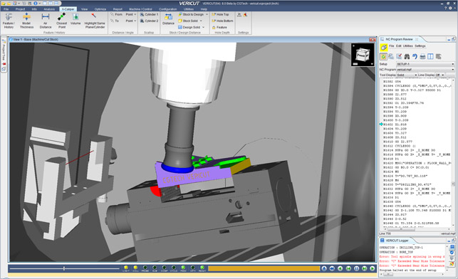
There’s also a log window at the bottom of the UI showing errors as a list (using colour coding). Selecting one of those errors not only snaps you to the point in the G-code where it’s created, but also switches your part viewing window to that same time in the program as well — affording you a view of pretty much everything that might cause an error, which means you’ve got an immediately more useful set of information on which to base your fix.
It might be that you apply a simple tweak in the G-code, make an adjustment on screen or that you go back to your CAM system and try to fix it at the source.
The use case will depend on how your best practices are established. I would imagine most smaller organisations would apply a fix there and then inside Vericut, while more heavily regulated organisations or those with multiple team members involved in the process, would chose the “back to CAM and fix” option.
The point to realise here is that Vericut isn’t just running a simulation of the G-code, it’s doing much more.
As a result, it’s able to pick up a greater level of potential errors that might not necessarily be represented in the G-code and simple cutter and stock simulation. That could be collision with other parts of the machine, that spindles haven’t been turned out. It’ll also do a solid job of ripping through any syntax errors in your NC program.
Vericut brings new additive manufacturing support to its 30 years of development for CNC machining verification
X-Caliper for measurement
Another feature that’s seen a lot of development since its release is X-Caliper. This tool allows you to take accurate measurements of your cut part against the nominal CAD model — both for remaining stock or to discover if the part has been over machined anywhere.
What’s interesting is that the ‘CAD’ model doesn’t need to be the traditional solid model at all, instead it could be a set of surfaces, a turned profile or, indeed, a cloud of points, which is particularly useful in the turbo machinery industry for checking aerofoil-like shapes.
While the ability to measure remaining stock across a model is pretty standard in most CAD systems, the level of detail is often lacking. This takes it to another level of depth of understanding as to what exactly is going on in the manufacture of your part.
CNC grinder verification
Another major update in the 8.1 release is the integration of CNC grinder dressing verification. These tools have been developed in partnership with a household name in turbine power generation to address a need that’s both very specific and very complex.
Where most CNC simulation and verification processes assume that there’s little wear on the cutter during each operation, the use of grinding is very different.
Vericut’s new tools allow you to simulate the CNC grinder dressing process while factoring in that the grinder wheel will reduce in size as you perform your operations. I realise that this is specialist in nature, but the fact that it’s available shows that not only is CGTech addressing these issues, but also that the use of more exotic alloys is becoming more commonplace and grinding is gaining use as a means of removing material.
The tools are targeted at both CNC grinding specific machines (such as Makino’s G5 and G7) as well as other multifunction machines that might incorporate such grinding operations.
CNC Grinding is now supported in greater depth in Vericut 8.1
NX interoperability
Alongside the standalone nature of Vericut, there’s also a case for using the system next to your CAM application — particularly when finding and resolving errors in CAM tool paths and needing to fix them in the generating system.
This is where greater integration with those tools comes in handy. One integration that’s been given some focus recently is how Vericut interacts and interoperates with Siemens PLM’s NX system. This is a particularly popular system in the aerospace field, where Vericut is widely adopted.
With this release comes NX connect, a tool that allows Vericut to talk direct to an NX session. If you find an error in Vericut, the system can launch an NX session and load it directly to the point in the NX CAM tools from where that error originated — allowing you to tweak it natively and rerun the verification more quickly than ever before.
There’s also been some work done to bringing Vericut into the managed environment of Teamcenter to solve the issue of traceability with the Vericut data alongside the originating, managed NX data.
In conclusion
Machining has always been a complex business, but today’s machine tools are more sophisticated than ever before. This new and increasing level of complexity is going to need this type of verification not only to ensure that there’s a program that is secure (no crashes, no gouges), but one that then moves on to optimising their processes.
Vericut makes the process visible and allows you to see exactly what’s happening on your machine. With that visibility comes the ability to adapt the process, strip operations down and make more efficient use of your machine because once it’s there running thousands of part cycles, you’re not going to change it.
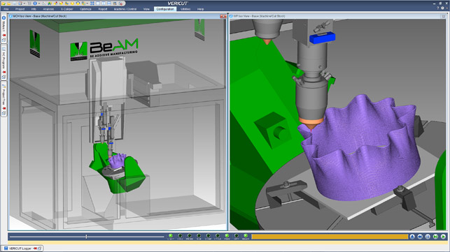
What’s interesting is how CGTech is also exploring new ground with its introduction of additive manufacturing support on the Directed Energy Deposition (DED) front, so users exploring these processes can gain a greater understanding of not only what their operations are doing, but the resultant quality of the part once they’re finished building.
Vericut now has options for verifying hybrid additive manufacturing/CNC machining processes
Vericut & Additive Manufacturing: Tackling the complexity
Stepping away from Vericut’s traditional focal area of advanced machining, let’s talk about perhaps the biggest news for the 8.1 release.
From this point onwards, CGTech is expanding the remit of Vericut to not only address machining in all forms but it’s also starting to include support for additive manufacturing. While many might sigh and think “of course, it’s all the rage these days”but, in this instance, there’s a great deal of substance and critical need behind the move.
The world of additive manufacturing is a curious place at the moment. Until recently, the majority of metals-based activity has been on the powder-bed approach, using a combination of lasers and metal powder to fuse together parts in a variety of powders. What’s changed is the wider focus on a process that, in effect, combines welding with a layer-based approach to build up parts.
Whether that’s a welding head mounted into an adapted CNC machine tool or mounted on a robotic arm, there’s huge research underway in many organisations to find a way for this to solve some particularly challenging engineering problems.
In the context of layer-based build up and CNC machines, something interesting is happening in terms of using the innate ability of these machines to simultaneously provide machining capabilities. This hybrid approach has a variety of names, but Direct Energy Deposition (DED) seems to be sticking.
Whether the material layer is enabled by high-powered lasers, an electron beam or plasma fusion, the concept is the same.
Here, the machine lays down the rough form or near-net shape using a CNC controller build head, then traditional machining techniques and cutters are used to finish or semi finish that part — either incrementally (which also has benefits in relieving stress build in the parts) or after the build is complete.
There are a small number of vendors exploring this space but, as you might expect, it’s coming from the higher-end of the machine tool market with DMG Mori, Mazak, Mitsui Seuki and the like jumping into the fray in the last year or two.
There are also a growing number of vendors developing build heads which can retrofit onto existing CNC machine tools, with the likes of Hybrid Manufacturing Technologies leading the charge.
Realising that this is a potential growth area, CGTech has started to introduce a set of tools that allow the user to simulate and verify these systems accurately, not only in terms of motion of the build head to ensure collision free operation, but also to simulate the forms that are built up firstly using an additive approach and then to simulate and verify the post or in-process machining of those forms.
So let’s step through the process and find out where Vericut could assist.
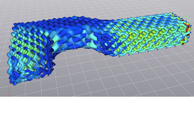
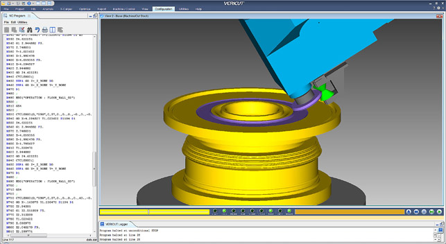
It’ll pick up areas of concern as shown in A and give you an accurate stock model as show in B
The first point is ensuring that your CNC toolpaths for the build head are depositing material where you need it.
Unlike traditional CNC machining, which assumes a 100% solid billet of material, when it comes to layer-based approaches, the build process means that there’s potential for each layer to have small pockets of material missing where the machine tool and associated program’s in-fill patterns miss areas.
As your part builds up, these could come to represent areas of potential failure in your part’s structure unloading. Vericut allows you to load in the NC code, simulate and verify it on a layer-by-layer approach, finding any potential problem areas.
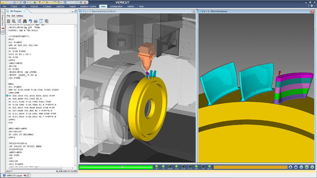
When looking at the external form of the part, these additive build processes create near net shape forms but, again, the layer-based approach means there’s more potential for areas to be missed or over built. Vericut will allow you to find these and use existing tools like auto-diff to find problematic areas.
The end result is a very accurate stock model on which you can verify the effectiveness of your subsequent machining operations — all using the tools that Vericut has had for over a decade.
The manufacture of parts using these advanced technologies holds some fascinating benefits, but with those benefits come some serious challenges.
The fact that you have a combination of two complex manufacturing processes crammed into a single, typically already complex machine tool, is bad enough. Then when you consider the number of variables at play in terms of not only tooling movement and verification, but also ensuring that your laser or plasma head is on and off when needed, material is being fed and gas is flowing, on a layer-bylayer approach, it’s clear that there’s huge potential for error.
There’s also the simple fact that additive manufacturing processes aren’t very quick. You’re looking at lengthy build times and discovering errors part way through or, worse still, after the fact is only going to make effective use of these powerful capabilities more essential.
Vericut Force: Optimising feed-rate based on physics
While we’ve discussed some of the enhancements and updates to the existing tools in Vericut 8.0, the release cycle also introduced Vericut Force. This builds on the toolpath optimisation tools already in your CAM system to optimise the feed-rate in a more comprehensive manner.
Optimisation in most CAM systems focusses on maintaining the contact between the cutter and stock and adapting the geometry of each toolpath to ensure constant loading. What they typically don’t do is analyse the feedrate in any great depth.
Vericut Force is intended to add to this an additional layer of optimisation by using FEA-based techniques to look at cutting force, chip thickness and spindle power to enhance the ‘as programmed’ to achieve a more constant feed-rate without altering the toolpath at all.
To achieve this, CGTech is working to characterise materials according to customer demand and industry trends, typically focussing on high-value alloys such as tool-steels, iconels, aluminium, titanium etc.
While much of this is baked into the 8.1 release, the 8.2 release will include a tool that allows users to character their own proprietary alloys assuming they have the capabilities available (typically done by running a predefined set of operations on a Kistler force measuring plate).
While much of the driver here is for quicker, more optimised toolpaths there are also benefits for tool/cutter life and for part quality perhaps due to less stress on the cutter, less vibration and better surface quality (meaning few finishing operations or hand finishing).
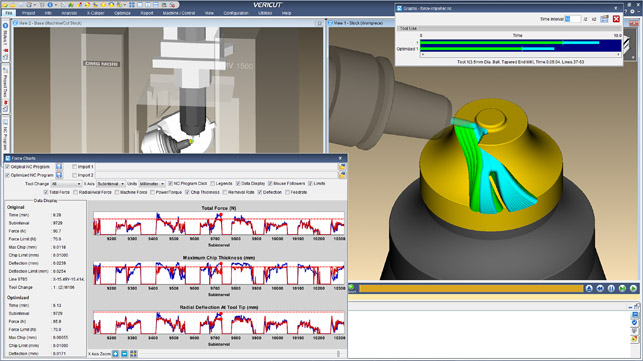
To use the Force, you begin with your operations and material defined in the system and then run the Analyse tool. This gives you a series of plotted charts showing machine forces, axis force, chip thickness, removal rate, deflection, feed-rate etc.
You’ll typically see areas where feed-rate spikes across the during of your program. You then run Optimise. This will adapt the feed-rate to remove these spikes and smooth out those forces that place additional load on your cutter and machine tool. The system will then report back on the time saved and, if you have the information in the system, a saving in a financial value on machine tool time.
It’s worth noting that this does not account for cutter/carbide costs at all, so there’s typically additional savings in cutter life expectancy.
| Product | Vericut 8.1 |
|---|---|
| Company name | CGTech |
| Price | on application |


