
Autodesk Fusion 360 – A look at what’s been added, from expansion of generative design, through machining, and into the realms of electronics design
It’s been a while since we last caught up with Fusion 360.
If you’re not familiar with this product, Fusion 360 is Autodesk’s next-generation product development tool – a complete set of tools that covers common or garden solid and surface modelling and drawing production, but also supports many other tasks that sit alongside these core processes.
It includes, for example, T-spline-based sub-d modelling tools for definition of organic and complex surface models; a range of simulation tools, covering static stress and modal analyses, along with more complex physics and optimisation; and tools for mesh handling, rendering and visualisation.
It also extends into CAM and machine tool programming – not just for milling, but also for turning, laser/plasmacutting and more.
In recent times, the team behind Fusion 360 has also worked hard to flesh out a set of tools for generative design, allowing users to explore design space and manufacturing constraints in a very efficient manner.
In short, there’s a lot going on here – and with most of these capabilities available for around £400 per user, per year, you’ll see this is by no means a run-of-the-mill design system.
Let’s take a look at some of the updates made in the last year or so.
General updates in Autodesk Fusion 360
One thing that quickly becomes apparent when opening up Fusion 360 is that while there are a stack of new features and functions available, a great deal of focus has also gone into revisiting and improving those that have been included in the product for some time.
The user interface has been freshened up and individual icons have been changed to make them more consistent across Fusion and Autodesk’s Inventor product.
You’ll also notice that workspaces have been consolidated in some areas.
For example, where previously there were distinct, separate workspaces for modelling, for surfaces (patch) and so on, these are all now to be found in the ‘design’ workspace, albeit in separate tabs.
Smaller updates have made Fusion 360 more engaging to use and re-learn.
One example that springs to mind is changes to the core sketching tools, which are used to build almost every solid or surface modelling feature.
Previously, Fusion pretty much gave everything the same colour, with little differentiation between sketch entities, dimensions, constraints and so on.
Recent releases make these different entities easier to tell apart, making it clearer what’s going on with your sketch at any one time.
Moving on to more general design and engineering updates, a particular highlight is the ability to bend sheet metal parts up from a sketch, rather than creating flanges, as you would normally.
This makes sense if you’re creating a sheet metal part from a drawing imported as a DXF (perhaps from a legacy system), or if you have a number of bends that you want to control parametrically.
These processes can now be driven from a single sketch.
Eagle comes to Autodesk Fusion 360
When Autodesk acquired CADsoft, developer of the well-known and widely respected PCB design system Eagle, back in 2017, many wondered what the future might hold for a system beloved by hobbyists and professionals alike.
Since then, Autodesk executives have provided more detail about their future plans for Eagle, which provides those working in PCB design with tools for their full workflow, from schematic-level development to board design and layout.
If you’ve done that kind of work yourself, you’ll know that it’s a curiously two-dimensional process and a hard task to finagle design work into a threedimensional product.
To make things easier, Autodesk first added integration between Fusion and standalone Eagle, enabling Fusion to import Eagle board layouts and automatically create 3D models of them. Recent work takes this much further.
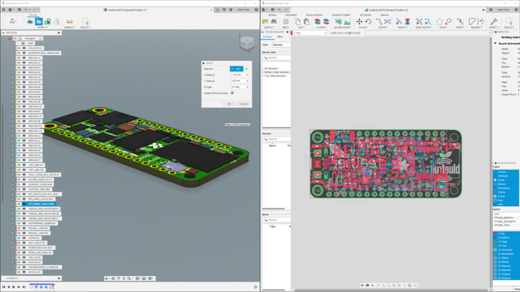
Now, when you start up Fusion 360, you’ll find Eagle integrated directly into the Fusion environment.
If you’re an existing Eagle user, you’ll find the tools you want in the File menu, allowing you to start a new electronic design.
This fires up a slightly reworked and refreshed version of Eagle, directly inside Fusion.
Since data, as you might expect, is stored on Autodesk’s own cloud servers, it’s available to the colleagues and partners with whom you’re working, as and when they need it.
My knowledge of PCB design tools centres on the reuse of data in the context of mechanical design and packaging, so these are the workflows I’ve focused on – and it’s where the benefits of having Eagle integrated inside Fusion really come to light.
At the click of a button, you can take your PCB design developed in Eagle and create a 3D model to be used by those responsible for mechanical design.
If you’re ever used an IDF-based translator or other 3D-aware PCB design system (such as Altium, for example), you’ll know that these models tend to represent a PCB board, at a fairly basic level, in terms of offering an accurate representation of traces and components, but only as primitive shapes.
This is what you get in the first instance from Fusion, too – but it’s worth noting here that with some background work and use of libraries, it’s perfectly possible to have the system populate the primitive ‘blocks’ that represent each of the ‘packages’ on a board much more clearly.
There are tools to automate much of this library creation and, of course, you’re able to use all of Fusion’s modelling tools to build them up yourself.
(What’s not 100% clear, however, is to what extent you can use the wide variety of online 3D component model libraries out there, in order to download and reuse that data, and save yourself the effort of modelling components up manually.)
If you’re using a PCB model of a supplied part, chances are that you’ll just need this 3D representation and that’ll be it.
However, if you’re working alongside your electronics team, you’ll likely need to work in a more iterative manner.
Here, the close integration between the mechanical design tools in Fusion 360 and Eagle makes huge sense.
Any updates made to the schematic or board design can be quickly fed back to the mechanical team. (Remember, it’s all on the Fusion cloud, so data management is handled automatically.)
Conversely, the mechanical design team is able to adjust the position of components, make required edits to the board and feed those changes back to their colleagues on the electronics team – again, this all happens in a managed environment.
Generative updates
Last time we looked at Fusion 360’s generative design tools, these had only just been released to the user community.
In the time between, these tools have continued to evolve and mature.
As you’ll recall, the system includes a set of manufacturing constraints that allows you to explore forms that are readily manufacturable (in terms of geometry) using machining.
Recent releases have seen additional manufacturing methods supported, so Fusion now supports 2-axis cutting, as well as die casting.
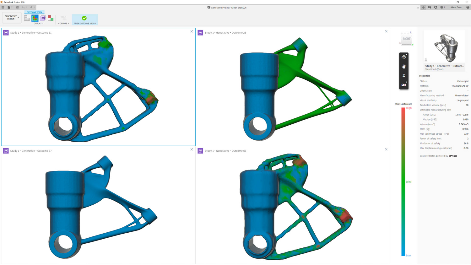
Another more recent update also brings cost estimation on board, which is based on technology licensed from aPriori Technologies, a fairly recent Autodesk partner.
This looks useful, but at present, estimations are only applicable to additively manufactured components.
While the cost estimates produced by such technology are always going to be ballpark at best, this inclusion does mean that you’re able to plot cost as a factor in scatter plot visualisation methods, measuring them against more mechanical performance metrics such as mass, stiffness or factor of safety.
Expanding capabilities
In the last 12 months, we’ve seen some pricing and bundling adjustments made to Fusion 360.
When we last looked at the system, there were two pricing levels: Standard and Ultimate.
These have been abandoned, in favour of single offering priced at just over £400 a year.
That’s for almost everything in the system, from CAD to CAM and all points in between.
But this doesn’t in fact tell the whole story, because at the same time, Autodesk has introduced the idea of ‘extensions’.
At present, these extensions add more specialised tools to the CAM offerings in Fusion, many of them drawn from the former Delcam technology stack.
They are paid for separately, on a month-by-month basis, using cloud credits.
To give you a flavour of what’s available, extensions include probing operations, steep/shallow machining (which comes from the mould and die machining world to help handle complex cores/cavities and so on) and some additive manufacturing-related tools for set-up and pre-processing of builds.
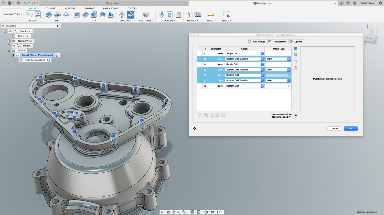
One particular highlight, for those with an interest in machining, are the Hole Recognition tools.
These don’t rely on natively defined holes; instead, they perform a geometry analysis of hole-like forms in your part and present you with a list of the grouped holes they have identified, along with best guesses as how you want them treated (which can very quickly be adapted to your requirements) and generation of toolpaths.
These extensions are all available for 125 cloud credits per month, so you only buy them when and if you need them.
The price equates to $125 per month, so it’s a question of whether there’s value there for you.
If you’re regularly performing probing and surface inspection tasks or work with parts with a lot of holes, then for those functions alone, I think the time savings achieved would justify the extra outlay.
In conclusion
Fusion 360 is looking good – but updates over the course of this year prove that there’s still plenty of scope for improvement in this product.
What’s interesting is that the team behind this product is expanding its remit beyond pure product design and mechanical engineering.
Yes, Fusion 360 has already achieved that goal, to some extent, with the inclusion of simulation and manufacturing tools, but it’s now moving into the realms of electronic design – a field that’s increasingly more closely associated with the mechanical design world, in terms of both workflow and data exchange.
I’ve probably written enough previously to convey just how much of a fan I am of Autodesk’s approach to generative design – so it’s good to see the manufacturing methods supported by Fusion expanding and moving beyond pure additive to include more traditional forms of manufacture.
The introduction of cost estimation functions, meanwhile, is only going to make things more easy for users working at the most formative stages of design and engineering.
Alongside the shiny new features and functions, work done to address some of the workflow stickiness users have found in Fusion, as well as some of longer standing issues surrounding the user interface and the user experience, is excellent.
Better differentiation of sketch elements is a prime example of how existing tools can always be reevaluated and improved.
From talking to the team behind the product at Autodesk University in Las Vegas last winter, it was clear from what they we can expect to see a lot more of this kind of work.
Fusion 360 is still a relatively new system on the market, but one that is maturing nicely and finding its stride.
It’s also a system that isn’t afraid to push out into new pastures and explore new ways of helping design teams work more efficiently.
And, frankly, I’m still amazed at the scope and depth of what’s available for around £400 a year.


