
SimSolid – When it comes to simulation, large assemblies cause some serious headaches for those looking to perform efficient analyses. We explore Altair’s product which offers a unique solution to an age-old problem
Altair is a name long associated with some of the most advanced simulation technologies available, but in more recent years, the company has been exploring the potential to bring its tools to a much wider audience.
While this has predominantly been conducted through its solidThinking brand to date, the company also made an acquisition in October 2018 that expanded its portfolio significantly.
SimSolid is the flagship product of a start-up that had been around for a good few years before its acquisition by Altair. It’s based on a meshless method of simulating large, fully featured CAD models.
While the underlying principles around how the system operates are pretty hardcore, the basics are perhaps best understood via a walk-through example, so let’s dive straight in.
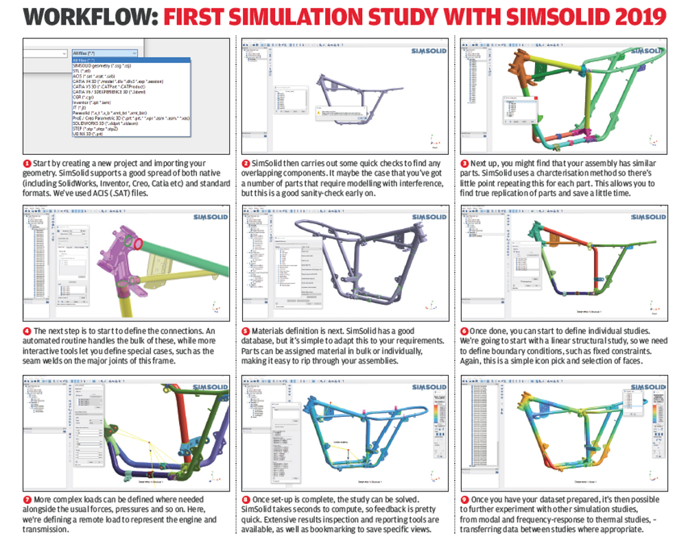
We’ll begin with the set up for a new study. SimSolid is a project-based system, allowing you to have, within a single project, multiple sets of geometry, multiple study types (it supports linear and non-linear structural, modal, transient and thermal analyses.)
For those working on more complex assemblies, multiple subsystems or indeed, rapid iterations during the early stages of design and engineering, this will prove invaluable for managing data and results.
As ever, the first step is to import your geometry. SimSolid has a good range of import options – from the usual suspects of STEP, IGES, SAT and Parasolid, through to some more native formats including Catia V4, V5 and V6, Inventor, Pro/E and Creo, Solidworks and Siemens NX. It’ll also read in STL files, but I’m not 100% convinced that’s the best format to use.
While most simulation systems would follow the path of importing CAD geometry (or building it from scratch), then giving you tools to mesh that geometry as the basis for the simulation, SimSolid differs quite significantly.
The need for a mesh has been removed, as SimSolid works directly with original, unsimplified geometry. During import, the geometry is classified, and special high-order functions are used to approximate the initial solution.
Proprietary adaptive analysis that locally enriches the functions is then used to further refine the result. This gives SimSolid both its speed and accuracy.
In some instances, this is purely down to shape, but in others, it will recognise form (such as bolts, washers, springs or thin sheets), as well as geometric features such as through holes. It will then define a lightweight physical model that represents a bolt, for example, in your assembly tree.
To the user, the geometry simply imports and displays on screen, allowing them to select, interact, view/hide and section it.
But behind the scenes, it is swapping out what would traditionally be a complex finite element mesh for a much more lightweight data model for each part.
SimSolid – defining connections
Your next step is a little more interactive, depending on the complexity of your product and how it is put together. You need to define the connections between all of its constituent parts.
As with most such tasks, you can apply an automated connection-finding routine to your assembly, which will find and assign those connections based on a global setting (such as ‘all connections are bonded’).
Of course, in many cases, there are more complex interactions between parts, so a good step is to define the special cases first, then apply the automated routine.
Our example projects, for example, feature a lot of welding, and SimSolid allows you to define these explicitly, either as seam welds or spot welds.
There are also tools to use bolted connections including pre-tension.
It’s possible to define remote masses where needed, which is very useful for defining supporting structures, without the need to model what it is that they’re actually supporting.
The last general task before you get into specific simulation studies is to define the materials in your assembly. As with all good simulation codes, SimSolid is supplied with a pre-baked selection of engineering materials.
This features both linear and non-linear material properties (since the system supports non-linear structural work) and, of course, you can use your own.
You can work through your parts by material grouping, selecting parts manually and applying the correct materials – or you can apply then as a whole, then pick out individual parts to edit.
In addition, SimSolid supports direct import of CAD-defined material properties for common applications such as Solidworks, NX, Creo and Onshape.
This set-up process is fundamental to getting good, accurate results out of the system. If you spend the time making sure everything is accurately defined here, you’ll have a solid base on which to conduct your studies.
There are tools built into help you achieve that, from simple randomisation of component colour (which helps with visualising what might be very complex models), through to more analytic tools to display and review disconnected parts and connections in place.
SimSolid – defining your first study
With geometry, materials and those all-important connections in place, it’s time to try out one of the simulation studies possible in SimSolid.
The system, as we’ve already mentioned, includes both linear and non-linear structural analyses – useful for both non-linear material behaviours but also non-linear geometry concerns (such as largescale deformation and so on.) Alongside these, dynamics use time, frequency or random response including base excitation.
We’re going to work through a linear structural analysis of an older motorcycle frame.
While this isn’t a huge assembly in terms of the number of parts, setting this up in a traditional simulation system would be more than a little difficult once you factor in different materials and connection types (such as bolts, welds and so on) and the curious loading conditions.
As you start a new study, all of the information you’ve already defined transfers into a new folder in the project tree. You’ll spot that SimSolid has placed your materials and connections here – but if needs be, these can be overridden where appropriate for your study.
As we’re working on a structural simulation, we’ll now need to define the boundary conditions for that study – the usual constraints (in terms of where the assembly is fixed) and the forces, pressures, loads and so on.
SimSolid has a clear workflow for these and you define each set of boundary conditions using their own dialogues, selecting the appropriate command from a vertical toolbar to the right of the main modelling window.
These separate dialogues mean it’s very quick to start adding fixed faces, for example; the dialogue pops up and you navigate around the model, selecting each face.
There are tools to tangent faces to those selections and you can very quickly build up your list shown in the dialogue. Hit ‘apply’ and it’s done – with a new entry added to the project browser.
While other mainstream tools might require selection using the familiar CTRL and mouse selection method, the listing is more useful, allowing you to remove misselected faces, points or other geometry with ease.
SimSolid’s structural tools have a good set of boundary conditions available, covering most of the basis – fixed, sliding, hinge and pivot constraints. Loading conditions range from the usual suspects of force and pressure to the likes of bearing, gravity, remote mass loads, thermal loads, hydrostatic and nut and bolt pre-tension loads.
Once you’ve completed your set-up, you can run a quick check, although this just to ensure that you have a fully connected assembly and the minimum viable boundary conditions defined.
Then it’s time to move on to calculation – and this is where things get really interesting. If you’ve used simulation technology before (with a few exceptions), you’ll be aware that the cycle of ‘CAD to mesh to solve’ is often a lengthy one.
The solve part alone can vary from minutes to hours, if not days, depending on the complexity of your mesh and your study requirements.
SimSolid, by contrast, doesn’t really have a solve step, as this process happens in a matter of seconds. For example, our linear structural study took just three seconds to solve.
Yes, as your studies grow in complexity, so will solve times, but these are delivered an order of magnitude faster than is the case with most traditional systems.

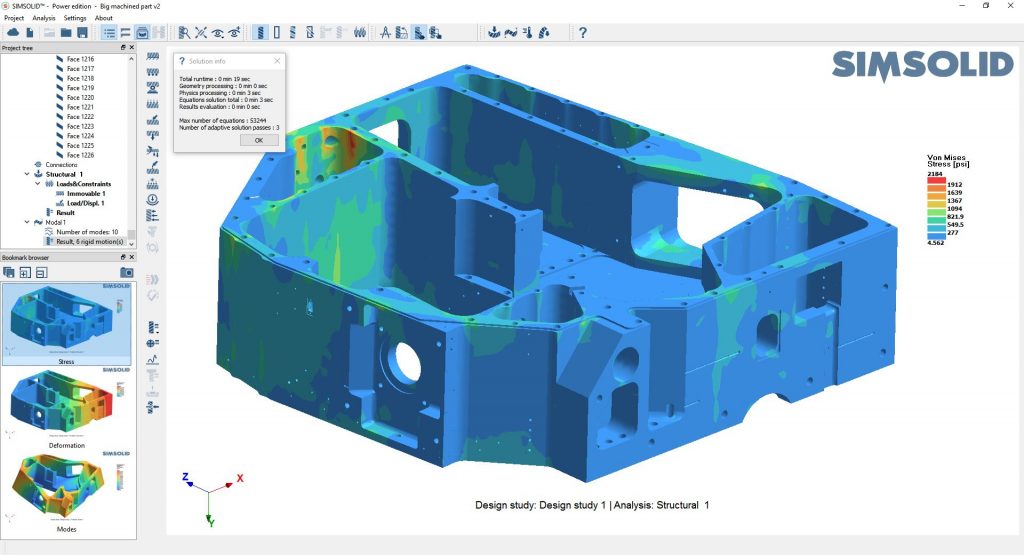
SimSolid – results interpretation
Results inspection comes around a lot more quickly with SimSolid, so it’s a good job that this stage is pretty simple to dig into.
At the bottom of the same vertical toolbar, you’ll find the results operations. The first port of call will be the ‘Results Plot’ icon.
This expands to give you a range of other tools for plotting Von Mises, stresses, strains, displacements and the like – all as you would expect.
The legend that pops up into each plot type is fully interactive, so you have tools to finetune display, output (in terms of units, deformation scaling), minimum/maximum bounds locking, as well as animation tools.
Of course, these vary for each simulation type, but the basics are all the same.
Below your plotting options, you’ll then find tools for individual point inspection, graph plotting, bolt/nut resultant forces and more.
And this is what’s key to SimSolid: on the surface of it, the system seems very easy to use. And often, in the simulation world, that’s associated with ‘not much functionality’, but once you dig into each icon for results display and model interrogation, it’s clear that you can pull useful data out of your simulations, rather than just generate pretty pictures (which it also does, by the way).
Other study types
While we don’t have space to detail every study type that SimSolid currently supports, it is worth detailing the additional types of work you can do with the software.
As well as linear and non-linear structural studies, you can also move into modal simulation.
Again, these studies are simply defined from your existing dataset. You can transfer items from a structural study where appropriate (such as fixed constraints and so on) and tweak where needed.
You then tell the system the number of modes you want to discover, and the system brings your answers back in seconds. As you’d expect, the results interpretation tools allow you to dig into results.
Alongside modal studies, you will also find opportunities to explore transient, frequency and random-response studies, and finally, thermal studies.
In conclusion
SimSolid is a cracking simulation tool for those looking to simulate the performance of large-scale, complex assemblies, but in a timeframe that makes simulation a regular aspect of design and engineering – something not readily available elsewhere.
What’s interesting is that this time reduction is not really about the time to compute results, either. It’s more about being able to use your design and engineering geometry, as is, without having to first spend hours defeaturing and simplifying it and eventually meshing it, before then having to go through all of the set-up work to get to the point of hitting ‘solve’.
While there will always be a set-up and a solve time cost to simulation, being able to simply use your CAD geometry is much more efficient. It saves you all that time and, chances are, you’ll be more inclined to run multiple studies, multiple design iterations or variants through the simulation process.
So your time savings quickly add up – or perhaps more critically, the same amount of time is used, but you learn a lot more and your products get better as a result.
Then, if you consider the fact that solve times are measured in minutes at best, it’s clear why SimSolid has the potential to empower its users to an enormous extent.
There’s a fully functional trial available, so it’s worth downloading and throwing some data at it. I think you’ll be surprised at how efficient this system is.


