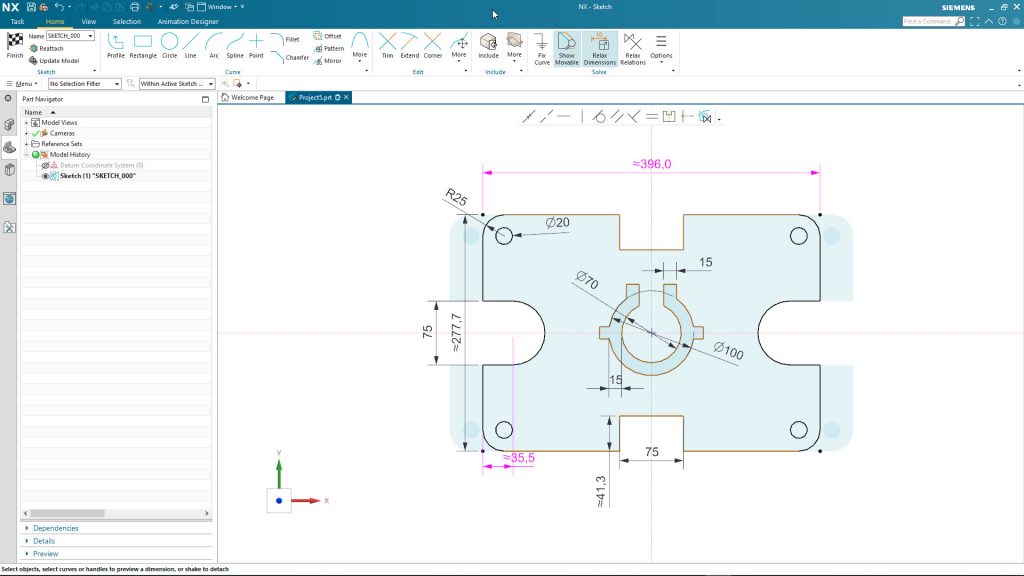
Siemens Digital Industries Software has just updated its NX product with a brand-new sketcher and it’s worth taking a closer look at.
And trust me, it’s not often that we all get excited about a new sketching tool, is it? After all, 2D sketch has been a core part of almost every 3D design system for decades.
While other methods (surface manipulation, curve networks, primitives and Boolean operations) exist, for the majority, using predominately history and feature-based, creating a 2D sketch is the starting point for almost every all modelling operations.
Consider how most sketchers work and have worked for years (if not decades): They’re essentially mimicking the technical drawing process.
You create your lines, circles and arcs to create the shape, then add dimensions to dial in the exact form you want.
Along the way, there have been key additions, such as constraints and relationships – whether added manually or inferred when sketching.
Over the years, a parametric element has also been added, allowing you to build in relationships between dimensions to drive the adaption of those sketches, both in reference to their own dimensions, but also across features in parts or, indeed, between parts or assemblies.
All good, all very clever and I’m sure something familiar to 80 per cent of DEVELOP3D’s readers.
So how does Siemens’ new sketching tool differ? The answer is both subtle and really obvious once you see it working – particularly for someone trying to write about it. So let’s do it with video.
Sketcher basics
To learn more, we’re going to work through a couple of videos, then discuss the content to gain a better idea of what Siemens’ development team has done.
Let’s start with a video that introduces the basics (voiced over by Siemens NX legend, Paul Bevan).
What did we see?
A pretty intuitive sketching and constraining workflow: Create your sketch entities as per normal, infer some of the relationships as you would in a traditional sketcher, then start to add in dimensions and such to nail things down.
Want to add a dimension to a line? Click the line. You’ll see that there’s a dimension popped into place. You’ll see the double tilde symbol next to the value. That means the system has generated that value – double click it and you can add your value.
If you want to add a relationship between two lines, select them and you’ll see an angular dimension pop into place. If it’s misaligned, drag it to where you need it.
Again, the double tilde shows you that it’s not dialled in. This is pretty standard compared to most sketching tools.
Then you get into the realm of editing those rough sketches into a more formal form. It’s at this point, of adding control to a sketch, that things are really starting to change.
In a traditional sketcher, you’d add constraints to nail down those values or relationships.
If you add a linear dimension on an edge, you’re effectively marking that as done, then move onto the others.
We’re all familiar with the ‘over constrained sketch” error message which can take moments to fix or, if you’re looking at more complex edits, 30 minutes of swearing, trying to find that one relationship that’s stopping you moving forward.
In this new sketching environment, things aren’t anywhere as near as rigid. You have flexibility in your sketches – you can break or relax relationships quickly and re-apply them where you need them. So shall we take a look at some more complex sketching workflows?
More complex sketcher edits
Let’s take a look at a slightly more advanced video with more complex design changes – and how you can make some more complex changes to the whole or just portions of a sketch.
You can see how symmetry is maintained, how portions of the sketch can be quickly adapted to suit new requirements – what’s interesting to me is that these changes are being made without heavy editing of the constraints in the sketch.
Just a quick click and they’re relaxed where needed – there’s very little delete/reapply workflow that could typify how these types of edits are made in a traditional sketching tool.
Imported Geometry
By now you should have a good grasp of how this sketcher works and what’s different. To round things out, one question that might be asked is how does this perform with imported geometry?
Whether that’s a sketch from a DXF or from legacy data, there are some slick workflows for rebuilding components intelligently, using an imported set of profiles as the basis.
In the video below, you’ll see how the system can work with imported geometry and how the new sketch solver is finding relationships that are pretty complex. We’re not just talking finding horizontal or vertical relationships, but arrayed features and more.
Final thoughts
This is probably the nerdiest post I’ve written in a long time. It might also sound trivial to discuss changes to a sketching tool in the context of 3D design in 2020. Surely, we’re done and dusted with this type of thing?
The answer is that yes, most design systems have a decent sketching environment and they’re all pretty much evolutions of how PTC started doing things with Pro/Engineer. Smarter, sure. More intelligent, absolutely. But have they made the process easier or just added a layer of complexity that we could perhaps do away with? Also, very much the case.
What Siemens has done is, on first look, quite subtle and I’m sure I’ve done a pretty poor job of explaining that subtlety.
What I can attest to is that this makes sense – huge sense – it’s super intuitive and it just works, even during the most complex of edits to a sketch.


