
In our March 2010 article we used a free-body diagram to understand how the loads and moments varied within the chain-side crank of a bicycle.
Such diagrams are absolutely essential as they not only describe the load path within the structure but tell us which stress calculation(s) should be carried out at any given location. Take for example the pedal axle – our free-body diagram requires that shear force (250N) and bending moment (9000Nmm) calculations are carried out at the threaded end – we will return to that calculation later. Free-body diagrams are the key to success (in statics and dynamics) so go and practice them!
Moving on, it is imperative to realise that the magnitude of load (on a structure) does not necessarily mean failure as a massive component can often tolerate a massive load. We need therefore to take account of the local concentration of load and to this end we think about “stress” which is defined as force-per-unit-area (ALL stresses are in the units of force/area). Irrespective of the size of the component we are considering, stress can be compared with (say) the yield stress, a fatigue limit or an ultimate failure stress. Stress then is an excellent measure for the engineer to quantify.
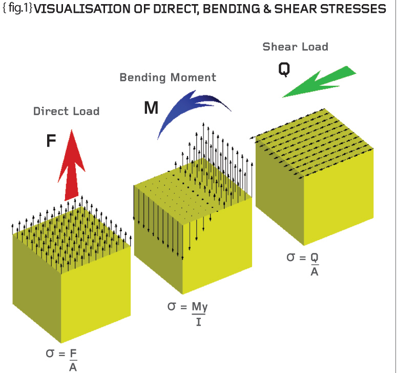
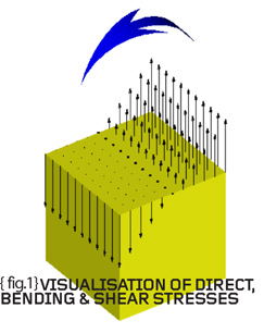
{fig.1} shows the three basic forms of loading (direct, bending and shear) and how these induce a certain stress variation within a component. Direct loading (loading in the longitudinal direction) causes a constant stress variation equal to the direct load divided by the original (unstressed) area of the cross-section. {fig.1} shows an upward direct load, F, which causes tensile stresses – equally the load could be downward causing compressive direct stresses. The engineering sign convention is such that tensile stresses are positive and compressive stresses are negative.
Staying with {fig.1} it can be seen that a bending moment, M, results in a stress variation which changes from tension at one edge to compression at the other. The stresses are “direct” (normal to the section of interest) but vary in a linear fashion and are zero in the centre of the section.
Bending wreaks havoc in structures so we will return to the subject next time but for now just accept that the peak surface stresses are given by +My/I or –My/I (where M=bending moment, y=offset from the centre, and I=second moment of area).
Finally {fig.1} shows a shear force, Q, acting in the lateral direction. The resulting shear stresses also act in the lateral direction and the average shear stress is equal to the shear force divided by the area being sheared. The same definition as that used for direct stress except this time the stresses are in the plane of the section being considered.
{fig.2} Cartesian stresses xx, yy and xy
{fig.2} shows an infinitely small “chunk” of structure defined in a rectangular Cartesian (from the work carried out by Descartes 1596-1650) coordinate system. Our established ideas of equilibrium must still hold so we can draw a direct stress xx to the right and an equal and opposite stress to the left. We can do the same in the y (vertical) direction. Note also that two of the shear stresses cause clockwise rotation and the other two cause anti-clockwise rotation – the small “chunk” is therefore in force and moment equilibrium.
We need not get too engrossed except to say that the direct stresses have repeated subscripts (xx, yy and so on) and the shear stresses have dissimilar subscripts (xy and so on). This is because the “ij” stress component acts on the “i-positive” face in the “j-positive” direction. Many authors use “tau” for shear stress and “sigma” for direct stress. Given that we appreciate the subscript notation then we can use “sigma” for ALL stresses noting that like subscripts are direct stresses and unlike subscripts are shear stresses.
As good, common-sense, engineers we need to realise that the notion of shear stress is only required because we have set out our stresses in a Cartesian frame of reference. Here direct stresses are only allowed parallel to the X, Y and Z directions and the concept of shear stress had to be introduced in order that direct stress at any angle could be catered for. More about this when we consider principal stresses but appreciate that a direct stress at (say) 45-degrees will tend to deform our cube into a lozenge shape (refer to the three thumbnails on {fig.2}).
Returning to the pedal axle we can determine that the shear stress (on all sections between the load point and the thread) is equal to the shear force divided by the area being sheared. If we assume that an 8mm diameter axle is used then the average shear stress is approximately 5MPa ([250 x 4] / [ x 64]).
{fig.3} Direct Stresses xx on a bicycle crank
Finally {fig.3} shows the Finite-Element Analysis of a pedal crank similar to that considered last time. I have shown the direct stresses in the global X direction (xx) in order to illustrate that the bending causes tension on the upper side of the crank and the compression on the lower side.
More next time when we will perform hand calculations and Finite Element Analysis on a classic karabiner, which, for the unitiated, is a device used by climbers as a rope-joining mechanism!
{encode=”bj@damt.co.uk” title=”bj@damt.co.uk”}
Part three of an engineering master class, this month: Cartesian Stresses


