
In the previous article (#15, DEVELOP3D October 2011) we balanced the loading and then applied a 3-2-1 minimal constraint.
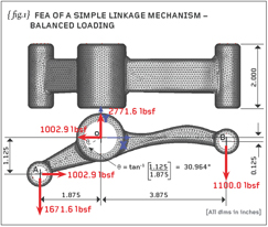
So, let’s firstly remind ourselves of the problem at hand: {fig.1} shows a side elevation of the linkage with the loads acting on it.
If you did the previous homework you’ll have proved to yourself that the linkage is under force and moment equilibrium. T
he applied loads will cause stress and strain but, without constraints, we currently have a structure that is free to drift around in space. We therefore need some sort of constraint to render a unique set of displacements BUT not so much constraint that we falsely stiffen the linkage.

To solve this we then applied a 3-2-1 minimal constraint, which restrained the linkage from movement with the lightest touch possible. A quick check of the summation of applied loads (and reactions) will show that these are near-zero as required. The stress results from this model (although not shown here) indicated a very localised P1 stress peak on the blend between the long arm and the central boss (251,567psi) and a larger area of high stress on the long arm itself (124,206psi).
Let us now look at two alternative solutions. {fig.2} shows contours of the P1 stress when the main bore is fully constrained instead of our previous 3-2-1 constraint. Here the loads that were applied to the main bore are removed and replaced by a constraint in the X, Y and Z translational freedoms.
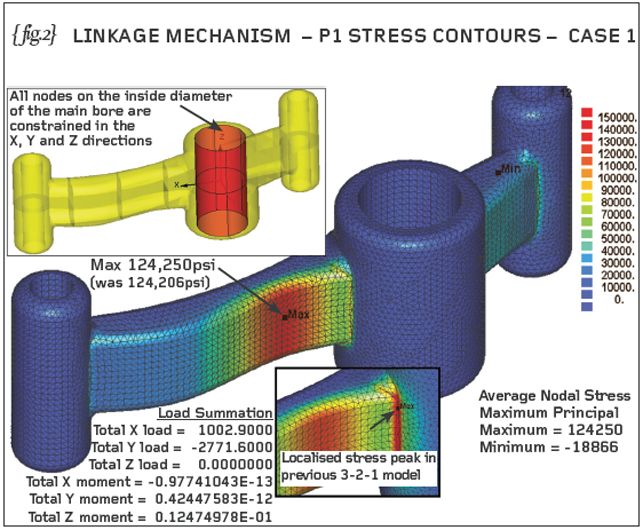
The loads applied to the minor bores, A and B, are applied as before and these loads show up in the load balance (and are reported on {fig.2}). The analysis produces a set of unique displacements but these are not realistic. In practice, with normal engineering tolerances, the central bore can ovalise, even a tight-fitting pivot pin will not constrain (the main bore area) as harshly as this.
The previously reported stress peak (251,567psi) doesn’t appear and the the worst area of high stress has now moved to the concave radius on the long arm where the P1 stress is 124,250psi. We’ve actually analysed two separate cantilevers!
For a second attempt, let us follow the advice of the NAFEMS 2010 publication – “How to – Analyse Practical Problems using FE Software – Volume 1” which explains how to solve practical problems such as this linkage. {fig.3} replicates the methods recommended in that publication.
Apparently the main bore must be able to rotate so a radial constraint is applied to all the nodes on the inside of that bore. The specified load of 1100lbsf is applied to the lower half of the minor bore B and a local constraint is applied to one side of the minor bore A.

The so-called ‘local’ constraint prevents movement normal to the line OA (see detail view of constraints on {fig.3}). In addition to these constraints we will need to constrain at least one node in the Z-direction and this has been done (the aforementioned book used a 2D plane-stress analysis where the out-of-plane freedom was not active anyway).
Again we see that the stresses local to the main bore are not realistic. The main bore diameter has been constrained such that it cannot expand or contract in a radial direction.
The main bore constraint allows rotation of the linkage and shrinkage/expansion in the length direction of the bore but otherwise the bore is over-constrained. The previously recognised peak stress of 251,567psi does not feature in this model and, again, the peak stress now occurs on the concave region some way along the longer arm towards bore B (124,258psi).
Given that we want a quick solution without the inclusion of contact with the various pivot pins, then the ONLY way to do this realistically is with the previously described method of balanced loading and minimal constraint. Over-constraining the central bore will stiffen the linkage and allow it to carry more load than it would be able to do in practice.
In both the analyses shown here the localised high stress (in the blend with the main bore) has been missed, potentially resulting in a design which may fail in service
We have spent the last three articles in this Engineering Workshop series (#14, #15 and #16) examining methods of support so I hope you can see the importance of realistic constraints and what happens when they are too severe. The ‘artistry’ of Finite Element Analysis is to apply constraints which prevent the rigid-body motions but do not over-stiffen the component or assembly we’re looking at. The aim is to use as light a touch as possible.
DAMT has produced 16 articles for DEVELOP3D, the first 15 were checked by John Horspool. I am grateful for his excellent input and advice over this period. Unfortunately John recently passed away.

He had been battling bravely against a terrible disease and leaves his wife and two children. John will be sorely missed, we have “put the world to right” on many occasions. The FEA community has lost a major player and campaigner. 
Part sixteen of an engineering masterclass: realistic constraints
Default


