Soon after the KTM X-Bow (pronounced ‘cross bow’) launched in 2008 I had the good fortune of being driven round in one on the Silverstone race track. When the driver put his foot on the accelerator it quite literally felt as though my stomach had dropped out onto the tarmac.
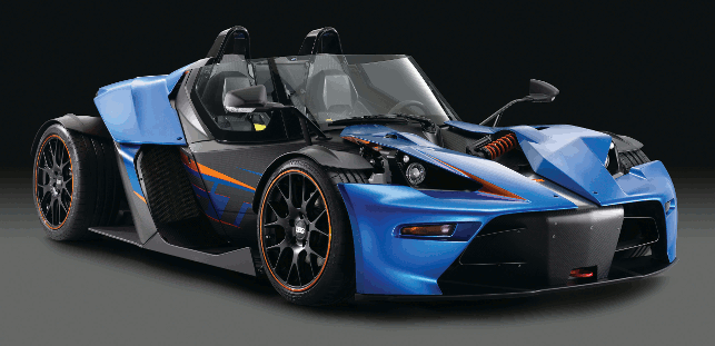
The KTM X-BOW is a radical, lightweight production sports car that demonstrates what optimising design and function using composite structures can deliver
Exhilarating is the word I remember thinking as the car was put through its paces. It most certainly lives up to KTM’s company motto of ‘Ready to Race’.
It was in 2005 that this Austrian company based in Salzburg, decided to use its expertise in designing off-road and street motorcycles to develop a highperformance racing car. The aim was to combine the acceleration of a motorcycle with the road holding of a race car.
The first X-Bow prototype was unveiled at the 2007 Geneva Motor Show and at the following year’s show, the production-ready version was launched. Today around 1,000 models of this road legal car are produced each year from KTM’s factory nearby Graz, Austria.
Since 2008, the car has been developed further. New developments include a lightweight yet high strength monocoque and a GT version. This monocoque and various other components, such as those that mount the windshield onto the monocoque, are made out of carbonfibre reinforced plastic (CFRP), a composite material created by combining carbon fibres with a plastic matrix using multiple layers (see box out below).
Advanced materials
The company responsible for the development of the X-Bow is KTM Technologies.
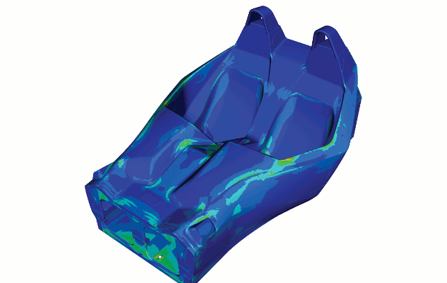
Evaluating failure criteria for all layers in the monocoque using Ansys
Part of the KTM Group, this arm of the company focusses on fibre-composites engineering for KTM projects as well as for other clients.
“Our aim is to develop lightweight CFRP structures in the automotive context as well as other industries such as sports equipment,” explains Martin Perterer, head of research and simulation at KTM Technologies.
During the development of these high-performance structures KTM Technologies utilises Ansys simulation software, specifically Ansys Composite PrepPost, which allows the engineers to predict how the structure will operate in the real world.
“The first monocoque designs of the KTM X-Bow were engineered without the use of Ansys Composite PrepPost.
When we did employ the software, we were able to reduce the monocoque’s weight – a very important aspect of sports car design – by 20 per cent,” comments Perterer.
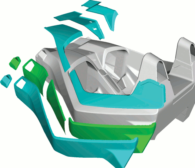
The composite monocoque exterior shell has more than 300 pre-cut layers
With a monocoque design, the external skin provides the main structural support – like an egg shell – as opposed to an internal frame. This approach provides the required structural loads using a composite layer design – up to 300 layers in some parts.
Using Ansys Composite PrepPost, KTM engineers can investigate the directional dependencies of these various layers, physical properties and possible layups, fibre orientations, and other variables.
All the details could be precisely analysed and simulated during the concept and development stages allowing decisions to be made early before committing major time and resources in the prototype and manufacturing stages.
Analysing loads
The Ansys tool was also used to analyse the failure behaviour of the composite design under different load scenarios.
As all the major components (including front/rear suspension and seats) are interconnected in a monocoque design, many different load cases were run to analyse static and dynamic loads.
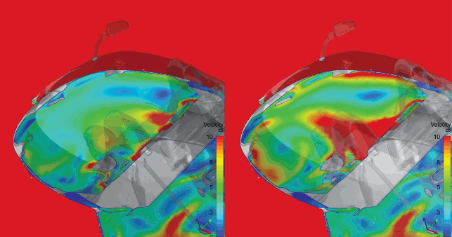
Using Ansys fluid dynamics software, KTM designed a wind blocker. Simulation was performed at driving speed of 140km/h, with red indicating higher velocity: air velocity with wind blocker (left) and without (right)
For example, the rear-engine mounting points on the aluminium rear frame must handle extreme forces, including torsional forces that occur when accelerating around curves by simultaneously going over potholes, for example, or going over curbs in the racing field.
The unique design for the X-BOW also used a torque arm directly connected to the carbon monocoque form.
KTM not only used Ansys computational fl uid dynamics (CFD) software for conventional aerodynamics, but also for shape optimisation of special components to ensure passenger comfort in the X-Bow by reducing the cockpit’s highly turbulent, high velocity
flow.
Audi e-BiKe
Being a consultancy, KTM Technologies is involved in a variety of projects but due to client confi dentiality these are all shrouded in secrecy. However, one that is out in the open is the work it did on the Audi e-Bike Wörthersee.
In 2012 Audi approached KTM with the brief of working with its in-house design team to create a concept electric bicycle that would push the limits of design, lightweight construction, e-connectivity and function. This high performance sport and trick bicycle would even have an automatic wheelie mode as an option.
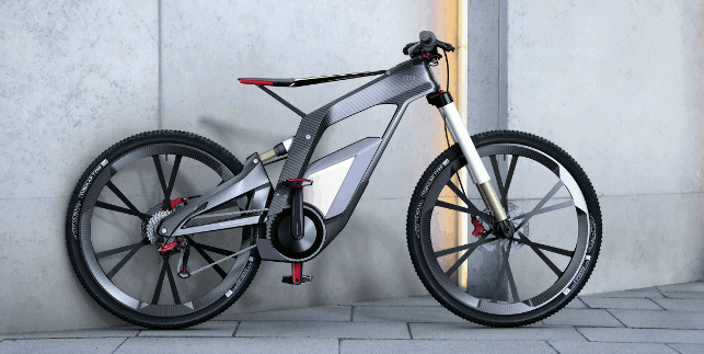
Following a design and development process of just 16 weeks, the Audi e-Bike Wörthersee successfully made it to its stand at the Wörthersee Tour car show in May 2012
KTM’s expertise would be utilised in the creation of the frame, wheels, handlebars and rear-wheel swing arm, which would all be made of CFRP. However, it didn’t have very long as the aim was to debut the new high performance e-bike prototype at the Wörthersee Tour car show in Reifnitz, Austria in May 2012, which was just 16 weeks away.
“Audi came to us with more or less a blank piece of paper. They told us what the main requirements for the bike were, what it should be able to do, what power the motor should have, what the weight target was etc. But other than that, it was totally free of design and together with the Audi design guys we developed everything until the final prototype,” explains Perterer.
All hands on deck
Of course 16 weeks is not very long at all and in order to be able to reach the deadline and deliver the prototype, the design team decided to adopt a holistic approach to the development process where all the different disciplines worked together at each stage.
“The 16 weeks was an intense time for everyone of us and the engineering was completely different to an ordinary project where you would have one or two years, for example, to develop a bike of this kind,” admits Perterer.
For instance, with CFRP structures a mould needs to be made, which in most cases takes around seven weeks.
This meant that there was not a long time at all for the upfront design and engineering. So, a conventional linear approach to the project would not have been possible.
“At the start every person involved in this project from design, engineering, production and assembly was around one table trying to make the design concept as straightforward as possible.”
Perterer and his team used Ansys Composite PrepPost to model and analyse the composite parts as well as analyse failure behaviour of the design for given standard loads as well as loads expected from sport and trick cycling.
The aim was to deliver optimal placement of reinforcement only where it is needed to manage static and dynamic loads.
The advantage of the Ansys tool in a development project such as this with a very tight timeframe is that simulations can be carried out from the early concept design phase using very rough 3D CAD models.
“A big advantage of Composite PrepPost is that we can generate our layup or different layups very quickly and look at where to put the fibres and in which direction. This enables us to perform parametric design studies very early in the development. In my opinion, this is a huge advantage of using the software.
“From there we can interact with our colleagues from engineering who are working on the CAD model to develop very quickly the main structural components,” comments Perterer.
Team players
However, even at the production stage all team members were still involved in the project to be on hand in case any issues did arise.
“So, there was interaction between every person at every stage. At the concept stage there were simulation, engineering and production guys and it was the same for the production stage because there was nearly a daily change in some area or another.”
But despite the challenges of a compressed development process, KTM managed to deliver the prototype, with its frame that weighs in at 1.6 kg, on time. In fact, they were two days early.
“Without Ansys Composite PrepPost, it would not have been possible to finish this project within the short timeframe,” admits Perterer. “We met all the requirements and the bike has done several shows now and everything works very well.”
Applications of CFRP
Carbon Fibre Reinforced Plastics (CFRP) have many favourable features over steel and aluminium.
BMWi3
The three key ones include: Lightness and strength — CFRP materials are lighter than aluminium, stronger than iron and have a higher elasticity than titanium.
Enhanced durability — They have a high resistance to strain and abrasion.
Low thermal shrinkage/ expansion — They have extremely low shrinkage and expansion against heat.
With features such as this, applications of CFRP are consistently growing. Examples of some of these applications include highrigidity parts in robot arms, reinforcement in drive shafts, panels for satellites, bridge reinforcements and rods in kite systems.
However, the industry where it is most often seen is aerospace and its use in aircraft structures.
For instance, composite materials in Airbus aircraft have seen a step-by-step introduction that started with the A310 in 1982. The recent Airbus A350 XWB is built of 53 per cent CFRP including wing and fuselage components.
Boeing’s Dreamliner 787 also features a CFRP airframe and wings. In addition to lowering the overall airplane weight, moving to a composite primary structure helps reduce maintenance due to fatigue when compared with an aluminium structure.
There is also a reduced risk of corrosion and fatigue of composites compared with metal.
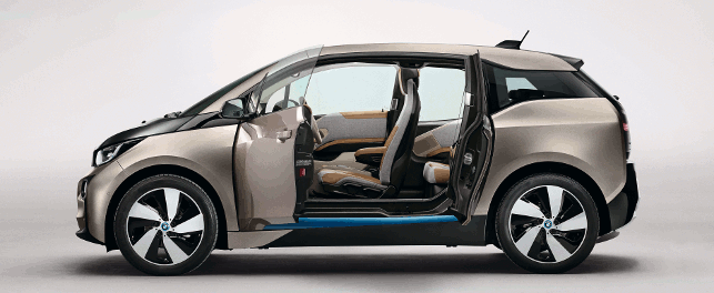
As is seen in this article, CFRP is also used in the automotive industry, predominately in sports and racing cars. However, with the roll out of the new BMW i3 (above) electric car, which features a passenger compartment made from CFRP, composite material has been used for the first time in volume car production.
The lightness of CFRP cancels out the extra weight contributed by the lithium-ion battery. It also faired very well in crash and impact tests with the deformation of the body being less than for a comparable sheet-steel body.
The production of the CFRP material takes place in Moses Lake in Washington, US, at SGL Automotive Carbon Fibres, a joint venture with the BMW Group founded in 2009, before being shipped to the BMW plant in Leipzig, Germany. The reason for that location is that the energy needed for the carbon fibre production is fully generated from hydropower.
In September 2014, BMW announced that SGL is going to triple the capacity of this carbon fibre plant. The site expansion, scheduled to be completed by early 2015, will make the plant in Moses Lake the world’s largest carbon fibre plant.
At present, the Moses Lake plant operates two production lines, exclusively for BMW i, with an annual output of approximately 3,000 tonnes of carbon fibre. A third and fourth production line is underway and a further two have been commissioned. This will triple capacity to 9,000 tonnes annually.
“As part of an intelligent mix of materials, we will apply carbon beyond our BMW i and BMW M models in the future,” says Dr. Klaus Draeger, board member purchasing and supplier network at BMW.
“Thanks to the pooling of the SGL Group’s expertise and our knowledge in largeseries production of CFRP components, we will be able to produce the ultra-lightweight, high-tech material also for other model series, at competitive costs and in large quantities.”
What is CFRP?
CFRP (carbon fibre reinforced plastic or carbon fibre reinforced polymer) is an extremely strong and light composite material, consisting of various carbon fibres and thermosetting resins.
CFRPs are commonly used wherever high strength-to-weight ratio and rigidity are required, such as aerospace, automotive and civil engineering, sports goods and an increasing number of other consumer and technical applications.
The composite consists of two parts: a matrix and a reinforcement. In CFRP the reinforcement is carbon fibre, which provides the strength. The matrix is usually a polymer resin, such as epoxy, to bind the reinforcements together.
The reinforcement will give the CFRP its strength and rigidity; measured by stress and elastic modulus respectively. Unlike isotropic materials, such as steel and aluminium, CFRP has directional strength properties.
The properties of CFRP depend on the layouts of the carbon fibre and the proportion of the carbon fibres relative to the polymer.
“This material is highly anisotropic. This means that the amount of engineering needed to develop it is a lot because if you compare it to metals, metals are isotropic where you can estimate roughly how you have to build your structure but with CFRP, you really need to know where and how to align your fibres and in which direction so you can create a layup of different layers and fibres in different angles,” explains Martin Perterer, head of research and simulation at KTM Technologies.
“This is the main challenge with building very lightweight structures because if you put fibres in every direction and create an isotropic layup, let’s say, you won’t have a really big advantage compared to metal.”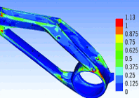
Ansys helps KTM Technologies speed up development of lightweight composite structures
Default


