
Inventor began life alongside Mechanical Desktop but now reigns supreme as the flagship product of Autodesk’s Manufacturing Solutions Division. In the near decade of its development, the system has moved from being a standard 3D modelling and drawing creation tool into a comprehensive design and simulation system and is now showing signs of becoming a capable manufacturing solution as well.
Through a series of acquisitions (Moldflow, Solid Dynamics, Plassotech and Algor), the company has been arming itself with a range of technologies that are only now starting to be added to the Inventor Suite of products. All of this is particularly evident in this latest 2010 release, where Autodesk has delivered enhanced simulation tools and plastic part design technology into the core Inventor product, mould design technology for Inventor Professional and the new Inventor Tooling Suite (which we’ll be concentrating on this month).

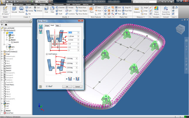
Inventor now includes a range of features that automate the creation of common, but complex plastic features, such as lips/grooves, mounting bosses, and grills
In line with these new developments, and helping bring the new functionality together in one consistent environment, is a new user interface based on Microsoft’s ubiquitous Ribbon. The new Ribbon-based User Interface (UI) is going to come as a bit of shock to existing users as pretty much everything has been re-arranged and, excuse my language, ‘ribbonised’. Commands and operations have been moved from the left-hand portion of the screen and reorganised into discreet panels that run across the top of the UI. The good news is that the work done sees the system reorganised so commands and feature-sets are presented in a very logical and workflow-centric way. The standard panels present groups of commands for sketching, feature-creation, assembly modelling and draughting. There are also additional panels for system options and variables (such as window control and display settings) as well as a whole host of learning tools that are going to be invaluable as users settle into the new environment.
Tool tips have been expanded and give users progressively greater amounts of information about commands as they hover over each icon. There’s also a direct link to the help system found in the quick access bar at the top of the interface.
Alongside the new ribbon UI, there are some key new pieces of functionality that are worth a mention. Inventor users should already be familiar with the ViewCube, which has been introduced progressively into each Autodesk product to provide access to standard views quickly. Below this there is a short vertical strip of view manipulation tools that let users set views, shading, and toggle between orthogonal/perspective, among others – all located in a very handy place.
Now, that’s the new UI dealt with, let’s look at the new functionality. Inventor 2010 is a pretty comprehensive update, so we’re going to look at the product in stages. This month, we’ll focus on the new tools for plastic part design, then deal with other areas in the next issue. Ready? Let’s go.
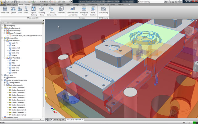
Mould base development is based on standard catalogues from the major suppliers but tools to adapt these to suit specific requirements and applications are also provided
Plastic fantastic
A major focus for this 2010 release is the design and manufacture of plastic parts, specifically injection-moulded parts. What’s interesting is how well developed the set of tools are, taking users through all stages, from the development of the parts through to core and cavity preparation, right into the realms of mould-base design.
In terms of new tools for Plastic Part design, the technology is based on development work done by Attilio Rimoldi (founder of ImpactXoft) and offers an intelligent method of creating plastic parts. This intelligence is not only in terms of how a history-based system handles and maintains a constant wall thickness, but also in terms of adding an impressive range of knowledge-based plastic part features that support the industry’s language and geometry types. The real key is the knowledge-based nature of these tools. They automate the creation of plastic part features that would previously have been repetitive and laborious to accomplish manually. The basic feature set for this release is mounting bosses (for fastener support and component mounting), grills and vents, snap fit hooks and loops, lips/grooves for part interfacing, rest features (where complex forms are required, again for mounting components or adding functionality to a part) and finally, rules-based filleting. Let’s look at a few examples to illustrate how they work.
Snap fits are common in many products and can be incredibly hard to model manually, particularly when they need to interface with complex forms. The Inventor Snap Fit feature provides an automated tool for creating both hook and loop type features. Once the basic positioning requirements are defined, the system builds the preview and allows adaptation of that form to achieve the required shape/functionality.
Another is the creation of mounting bosses. Open any injection-moulded component and you’ll find a series of plastic bosses. These are used to hold internal components, such as PCBs, in place and external forms together. Inventor provides a single feature operation for the creation of such features with a number of options to satisfy both functional and aesthetic requirements.
A final one worth exploring is rule-based filleting. These differ from standard fillets in that they are not assigned to specific model edges. Instead they are assigned to a feature (such as a pocket or boss) and the system calculates which edges need to be filleted with the user controlling how they are applied. While for simple geometry this won’t make much difference, the power of rule-based definition comes into play when handling complex design change and complex forms, as it makes the rebuilding of those features more robust.
Core/cavity to mould base
As with many features and functions within Inventor 2010 the new Tooling technology has been public knowledge for some time. However, rather than having been tried, tested and refined on the Autodesk Labs web-site (labs.autodesk.com), the technology has been on test in some of the most hectic tooling-heavy countries in the world – namely, China and Brazil. After all, if you have a new set of tools aimed at such a specific industry sector and working process, it makes sense to test it in an environment in which it’ll see a great deal of usage. While those directly involved with tooling design will be aware of many of the processes involved, Inventor’s new Tooling technology brings real benefit to those either making their first steps into developing moulds in 3D or those looking to gain a better understanding of the process so it can aid their design for manufacture knowledge.
With the new plastic part design tools and Moldflow functionality, Inventor now offers an environment in which to take your first steps into design for injection moulding
There is also the fact that, due to the rising costs and scarcity of many previously low cost and abundant materials (particularly metals), many designers are now engaging in plastic part design for the first time. By combining the new plastic part design tools with the full suite of design-to-manufacture preparation tools we’re exploring here, Inventor is now offering a capable environment in which to take your initial moves into design for injection moulding.
The process begins with the orientation of the part in question followed by the definition of material characteristics, and this is something particularly worthy of note. With the acquisition of Moldflow, Autodesk gained access to a much more extensive set of materials information (the company even has its own certified materials testing lab). This is now available within the Inventor Suite and there’s access to the fully searchable (by vendor, trade name, property) database of plastic materials, from which users choose a suitable plastic
Following this, features are added to the core and cavity, such as gate location, part processing settings and shrinkage. While users’ own knowledge and judgement can be used, the Moldflow tools also can be used to suggest alternatives. The key thing to remember is that these are guidelines and your moulder operator or supplier is likely to have a much higher-level of knowledge and know the intricacy of the hardware and the material and how they can be combined to achieve the desired results. At this stage, collaboration with your manufacturing team can certainly pay huge dividends. While these tools let users make a more informed decision, it has to be tempered with experience.
Once done, the work-piece size is defined and the geometry to split the mould insert or plates is created. Patching surfaces (shut offs) and run-off surfaces are created automatically, from the split-line. The automatic results will work for simple geometry but for more complex parts, users may need to adjust the surfaces or construct some manually. The final stage is to create the core and cavity solid bodies. Here Inventor uses all of the input for shrinkage, gating, shut-offs/runoffs to split the core and cavity. Everything is fully documented (including reports from any simulation runs performed). Next up is the creation of the mould base.
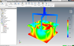
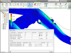
Since the acquisition of Moldflow, Autodesk has integrated simulation tools and materials libraries that allow users to discover how design and material decisions influence manufacturability
Again, the process is well defined as users move from defining patterns required for multi-part moulds, through definition of runners, gates, cold wells and cooling. As is common within tooling-focussed systems, everything is driven predominately by standard catalogues (Inventor Tooling includes DME, HASCO, Futaba, and LKM libraries) but custom sizes can also be created, depending on the project requirements. Once the basic mould configuration is in place, then users can move on to adding the components and sub-systems that make the system work such as ejectors, sliders and lifters to enable the moulding of undercut or complex features. Hardware is then added to link up the moulder, such as sprues and locating rings, or specific elements for cooling channels. The system provides a mix of tools that allow users to define these features automatically or dive in and add the geometry manually. Again, the integration of Moldflow technology at key stages lets users validate their decisions or they can have the system suggest new potential. Once happy with the mould they’ve designed, users can carry out the final 3D work to consolidate the core/cavity with the remainder of the mould tool.
There’s plenty of support for the various different approaches typically used, whether that’s a single piece plate to hold the part form, or single or multiple inserts for multi-piece moulds. Inventor has three different options to get the required form, and to add all of the various cut outs to ensure things are production-ready. Once done and ready, users can then move onto create the 2D documentation that’s required, not only for manufacturing, but also for assembly by shop floor staff. Inventor already has a wealth of 2D documentation tools and while there’s no way to automatically generate exploded views, users have the benefit that representations of the assembly are available (such as core half or cavity half, cooling channels and such) and much information can be extracted from the rich 3D model and the associated metadata.
In conclusion.. for now
What’s we’ve looked at this month is a very task- or process-specific set of updates made for the Inventor 2010 release. While the UI changes will come as a shock to the system for many existing users, I have to say I’m impressed with how it’s been implemented. While I’m not a huge fan of the Ribbon toolbar, you have to admire it purely for its ability to concentrate your mind on the task at hand. The interface adapts to the process or task you’re working on and I found there’s much less hunting around for icons.
Inventor 2010 features a new user interface based on Microsoft’s ubiquitous Ribbon, which helps
bring all the new functionality together in one consistent environment
As for the huge amount of work done to support not only the design of plastic parts, but the process of taking them through to production, I have to say that I’m impressed. It’s clear that these tools have been developed in a pretty rigourous and consultative manner and while many mainstream vendors have dipped their toes into mould design, it’s always been the specialists that have ruled the roost. But perhaps no longer?
I would hazard a guess that CAM is also going to feature quite heavily at some point soon. While there are many CAM vendors that integrate and integrate well with Inventor, you do have to wonder what the system would look like if Autodesk acquired a CAM developer and integrated those tools in a similar manner.
In terms of Tooling, by combining the new plastic part design tools with an impressive level and wide ranging integration of tools from Moldflow, Inventor is now offering a capable environment in which to take your first steps into design for injection moulding.
But what if you’re not directly involved in tooling design? Is there ground for adoption of these tools? In addition to offering real benefits to those making their initial moves into developing moulds in 3D, Inventor’s new tooling technology can certainly help designers get a better understanding of the process so it can aid their design for manufacture knowledge.
More next month when we look at the core updates for machine design, simulation and analysis. Stay tuned.
Coming up Next month: Analysis and simulation
Inventor used to rely on a parts-only Ansys-based technology for in-built simulation. This has now been replaced by Finite Element Analysis (FEA) technology from Plassotech, a company Autodesk acquired a couple of years back.
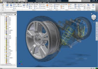
Finite Element Analysis (FEA) is introduced into the core Inventor product allowing for full assembly analysis
The technology has been introduced into the core Inventor product and allows for full assembly analysis. This can be driven from manual inputs, but a more intelligent way of working is to use the assembly simulation tools. These can be applied to work out how loads transfer between components in motion and with respect to time. That data can then be used to find maximum loading conditions and transfer all of the forces and loading data to stress analysis. It’s obvious that a lot of work has been done in this area, and one thing particularly worth highlighting is the breadth of optimisation technology now available.
While most FEA systems include some form of optimisation, Inventor now allows users to conduct design experiments where goals, parameters and variables for optimisation can all be defined, and various techniques used to find a smaller set of studies that will help get users as close to their goals as possible. It’s quick to find the variables that have the greatest effect and influence on the performance of the design, enabling the user to narrow down the geometry and get closer to the optimal in a shorter space of time. The review is can be found here.
| Product | Inventor 2010 |
|---|---|
| Company name | Autodesk |
| Price | from £4,200 |


