
Automotive manufacturers are using increasing quantities of aluminium forgings for their suspension systems in order to reduce weight and increase mileage.
In 2005, Kobe Aluminum Automotive Products (KAAP) started production in Kentucky to help meet this demand. It now manufactures around 280,000 components each month. The company’s customers
include some of North America’s major automotive companies.

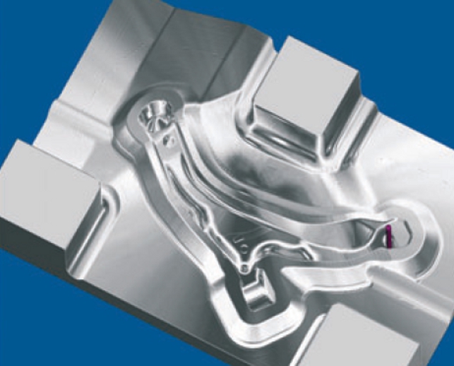
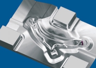
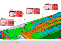
PowerMill simulations show the surface finish that will be achieved in the final die
KAAP’s greatest programming challenges are closed forging dies. These dies are used to produce parts with geometry ranging from simple to complex shapes, such as a half metre long link that starts
off shaped somewhat like a baseball bat, tapering down over its length to meet a larger diameter end. The end itself has a number of different radii that blend into each other.
“We were able to program these parts with the CNC software that we used in the past even though it was not very intuitive,” recalls Victor Steele, tool shop manager for KAAP. “Roughing operations
were relatively slow because the tools spent much of their time cutting air.” The most efficient way to rough out a forging die is to start with a large tool and use it to cut as much of the cavity as possible.
Then, you switch to the next size smaller tool and again cut as much of the cavity as possible.
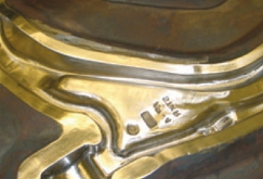
Final machined closed forging die
The problem with KAAP’s previous software was that each successive cutter traced the complete path of the part profile even when there was nothing for it to cut, either because the section had already
been finished or because the cutter was too large.
Kobe Steel’s Japanese operations had successfully programmed this type of die with PowerMill and recommended that KAAP try the Delcam software. “One of Kobe Steel’s programmers from Japan
visited us and showed us how to use PowerMill,” said David Taylor, engineer for KAAP. “Despite his limited English he was able to teach us how to use the program without a great deal of difficulty. We liked the way the user interface is laid out.”
Later, KAAP programmers had two days of on-site instruction provided by the local Delcam reseller, Design and Software.
“As we got to know the software in more detail, we were impressed with the large number of powerful machining strategies that it offers to help optimise cycle time and accuracy of machining operations,”
Mr. Taylor added.
“The big difference with PowerMill is that you can generate a stock model of the material left from the previous tool,” explained Mr. Taylor. “The software compares the material that is left on the workpiece with the geometry of the next tool and determines the areas of the part that it is capable of cutting. PowerMill then produces a toolpath that rapidly traverses directly to the areas that can be cut by the tool while skipping areas where there is nothing it can cut.”
“These rest machining capabilities save us a considerable amount of time, reducing cycle time by 40% to 45%,” Mr. Taylor explains.
“It now takes about 24 hours to machine a complete die or about two hours to machine a die repair.”
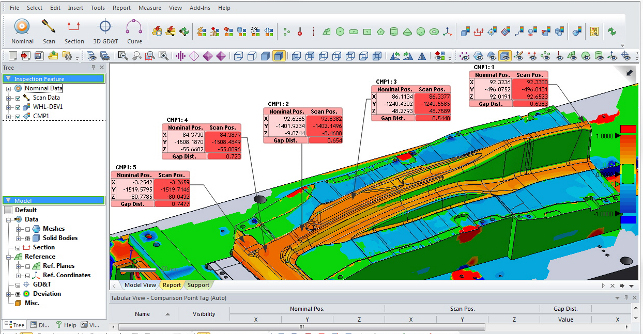
KAAP has also benefitted from PowerMill’s simulation capabilities. The software provides fully integrated simulation and collision detection, to ensure the CNC program is both safe and efficient, and also to predict axis reversals and surface quality.
“PowerMill has helped us substantially improve the efficiency of our machine shop operations,” Mr Steele concludes. “We have been able to substantially reduce the time required to machine dies and greatly reduced handfinishing times. The software is also much easier to use which saves time in training additional programmers.”
www.delcam.com/powermill
PowerMill cuts KAAP’s drilling time down to size


