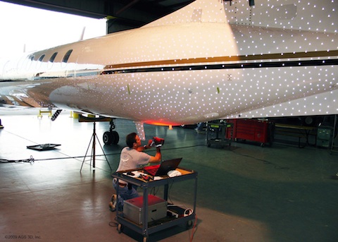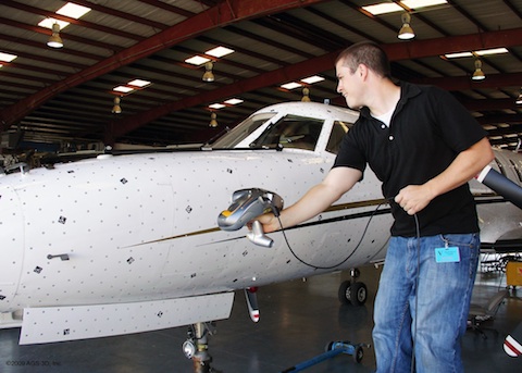
The Reflective dots you can see on the undercarriage of the plane assist with the registration of the scan data.
This just came in from Z Corporation, so I thought it was worth pushing up to the web straight away as it’s something I’ve been pondering of late. There’s a lot of talk about the mainstreaming of rapid prototyping of late and alongside rapid prototyping always comes 3d scanning – even Dr. Mings even discussed this yesterday on the Smack, with news of an 3D Photocopier, then of course there’s things like the homebrew laser scanner using the David software as well as the Next Engine. But while the mainstream is undoubtedly interesting in terms of proliferation of a technology to a hobbiest market (certainly not mainstream), there are times when you need an industrial strength solution to solve an engineering problem – and that’s never going to change. So, consider this (courtesy of Z Corp – but you’ll have guessed that already):
When a 30-year-old aircraft arrives in the hangar for retrofitting or repair, the more information you have the better. Yet engineering-quality design data can be elusive. The original plans, wherever they are, are often on paper and by definition in 2D form. Moreover, the same plane model varies from aircraft to aircraft because of manufacturing variations, modifications, damage or wear and tear. So from an engineering perspective, you don’t always know exactly what you’re looking at. This information gap has always been a reality and a cost of doing business for companies like M7 Aerospace, a Texas, U.S.-based aviation services firm that provides a full range of maintenance, repair and overhaul services for civilians, military and foreign governments.
Flying blind
Without precise engineering data, modifications can be time-consuming and expensive. Fitting parts and installing aftermarket equipment can be a case of trial and error. Anomalies can cause delays. Yet the need for service on older aircraft is pressing. Older, viable aircraft are often called upon to perform modern roles that may require modification such as avionics upgrades, cosmetic work, ballistic blankets, external sensor installations for missile defence systems, or all of the above.
Meanwhile, the traditional method for capturing 3D engineering data from objects – scanning – has, until recently, come with critical shortcomings. Most scanning technology still requires jigs, fixtures, tripods or mechanical arms for point of reference. Putting a plane in a jig or arranging and re-arranging tripods and mechanical arms around a large aircraft is a monumental undertaking. And after scanning the plane – which could take weeks, months or years, if attempted at all – a team has to use software to stitch together the mosaic of images, taking pains to ensure that each frame lines up with every other and is assembled in the proper order. In other words, scanning a plane has been untenable, until now.
Adopting the ZScanner 700 PX
All this changed when M7’s computer-aided design (CAD) services provider, AGS 3D, introduced M7 Aerospace to Z Corporations ZScanner 700 PX, a handheld laser scanner which makes this type of job much easier. The reason that job is easier is that the system can operate without much in the way of associated equipment – it’s handheld – just that. For those unfamiliar with the products, it’s a smallish form factor device that connected to a laptop and only a laptop. Using a combination of two cameras, a laser and a product stickered up with registration dots (these help the system to maintain position and registration), you can scan very large objects indeed. This is possible because the combination of the unit, the registration dots the scanner can maintain it’s own position in space, meaning you can get more complete scans, without registration of separate meshes, fewer set-ups and such.

The Scanner draws it’s power from the laptop connection (I seem to recalled it’s firewire for greater data bandwidth), so you’ll only wrangling one laptop and device as you scan.
M7 used the ZScanner to precisely capture the entire surface of a Fairchild Metroliner, in a resolution of 0.1 mm, in just three days. The Fairchild Metroliner is a 19-seat commuter-class turboprop aircraft with a 57-foot wingspan. The team first scanned the plane to create a “macro” photogrammetry model and then scanned it again using the laser scanning function. Thus, surface data was captured at the micro level in the context of the photogrammetry framework. The digitized object appears on a laptop screen intact, eliminating costly and time-consuming post-processing.
“Even if the team is operating multiple scanners and lap tops, the ZScanner brings it all together into one point cloud,” says Joe Furnish, M7 Aerospace vice president of engineering services. “No file repair is required. The software understands what it’s looking at.”
When the scanned file is complete, M7 imports the file into Catia as a parametric solid model editable [more on this shortly] just like any other part designed in CAD. “At this stage, M7 has its engineering information in hand, in 3D, and ready to use for quicker, more accurate and more economical service,” says Furnish.
With the ZScanner, M7 is now able to offer a new service to scan any aircraft – exterior, interior or both, creating precise, three-dimensional portraits of entire planes down to one-thousandth of an inch. This gives both M7 Aerospace and the plane owner the precise engineering data they need as well as an approximate design template for any plane based on the same design. “There’s a growing need for both our government and commercial customers to keep their older aircraft flying and productive,” says Furnish. “This new scanning capability helps us do that. By automatically capturing deep engineering data, we can more quickly and efficiently reverse-engineer aircraft and components that were originally designed in the 2D era – before 3D CAD was readily available.”
Now – Some of you might have noticed a couple things. Firstly I found this story interesting because it’s about a company expanding its offering and potential through the adoption of a technology, a product and a process – and that’s something we can all relate to. Secondly, devices like the ZScanner products solve a problem that’s ever present in the reverse engineering world, that of scale. Big parts or products don’t lend themselves to 3D scanning – and if you want to scan such large parts or products, your investment is typically similarly large. The PX variant of the ZScanner range has been specifically developed for large part or product handling – not so much the device, but the software that’s bundled with it (Z Corp include software, or license technology from AICON who specialise in this field).
Also worth noting is something that crops up in the press release. It states that the system provides a “parametric solid model editable”. OK. I understand that a solid model is possible from a 3d scanner, that’s perfectly acceptable. I can understand editable. You take a mesh from a the scan software, bring it into Catia and you can create an editable mesh. But parametric? Someone got carried away with themselves. Yes, it’s possible to use software tools such as Geomagic Fashion or RapidForm XOR/ReDesign (or indeed, SolidWorks built in tools) to take a tessellated mesh, create surfaces and features from your mesh data, but automatically, as if by magic from a laser scanner? Looks like someone got a wee bit carried away. Still, it’s a good story.


