
Siemens PLM has lifted the lid on the latest release of Solid Edge at its PLM World event in Indianapolis, this afternoon.
The company’s mainstream design and engineering modelling system is looking to gain better handling of mesh-based geometry (using Siemens’ convergent modelling technology also built into NX), topology optimisation, better tools around 3D printing as well as other updates across some of the add-ons for CFD simulation, CNC machining and dated a management.
Meshes and Convergent Modelling
Solid Edge ST10’s big ticket items are in many cases, enabled by the addition of Siemens’ in-house developed Convergent Modelling technology. If you’ve not heard about this yet, it was introduced into its enterprise-focused system, NX, in the last release (Our review is here).
For the last year or so, Siemens PLM has been talking about Convergent Modelling technology. As is now increasingly common, the Siemens development team has been exploring ways to bring mesh or facetted data into its design systems to work alongside more traditional solid and surface modelling technologies.
While much of this has been driven by the rise of the tessellated 3D printing formats (such as STL), it’s undoubtedly true that non-analytic, mesh-based geometry is becoming more frequently found or resultant from a number of processes; whether that’s exported and shared data, laser scanned or from simulation studies.
The goal is that mesh-based geometry can co-exist and interact with more traditional solid and surface geometry. While this isn’t a new endeavour (Delcam began doing this over 10 years ago with PowerShape), it’s still not common.
The Solid Edge implementation looks pretty well thought out. There are not just the import tools, but tools to do some quick clean up and patching (for filling holes, removing artefacts from scans or unwanted) features, surface fitting to swap out mesh regions for more traditional surfaces (including some nice surface trimming tools).
Once the mesh has been cleaned up, it can then be used as the basis for standard modelling operations using the existing tools – though as with NX, I’m sure there will be some limitations on what you can do with a mesh, this looks pretty advanced for a first release.
Topology optimisation
Alongside the core ability to handle meshed more efficiently, this release also has tools that allow you to conduct topology optimisation.
Again, following the lead from the NX, the Solid Edge team has also integrated Frustum’s topology optimisation engine. While there’s a number of topology optimisation solvers out there, Frustum’s is interesting due to the results you end up with.
It follows the usual workflow of modelling up your design space (including regions you need to maintain), adding in the boundary conditions (such as loads and constraints) and letting it work.
Most topology optimisation tools (and I have no reason to doubt that Frustum’s solver is any different) use an element mesh and the end result is a pretty rough triangulated mesh. Frustum’s solve doesn’t and gives you a much nicer form.
It’s a mesh, but with the additions we’ve already detailed above, this isn’t so much of an issue for Solid Edge anymore.
Just as a side note, even if you don’t have Solid Edge, you can experiment with Frustum’s technology by giving its solver a whirl in a cloud-based environment – sign up is here. Upload requires a STEP file, you define your boundary conditions and results cloud compute efficiently.
Additive manufacturing and 3D Printing support
This is still a hot topic amongst many of the 3D CAD vendors and Solid Edge’s team is no different.
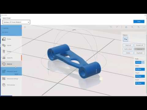
The ST10 brings a new set of tools that allow you to prepare your geometry for 3D print, whether you’re doing that using in-house facilities or using a service provider.
When it comes to in house workflows, the new tools allow you to arrange your parts on a build platform or bed, define tessellation quality, do some scaling work.
Solid Edge’s synchronous technology tools are already pretty sweet for pre-processing parts for 3D printing, particularly when it comes to splitting large parts for multiple builds (to split them up and add locating features) or adapting scaled down parts (where thin walls need to be addressed).
The demo shown shows you connecting directly to you machine if you need to connect to your machine (assuming its on the list of machines supported) – the reality is that you’re going to load the resultant STL or 3MF file from Solid Edge and run it through your set-up software anyway.
Perhaps more interestingly, as folks start to experiment with more exotic types of 3D print and additive manufacturing process, is Siemens’ tie up with 3freeyourmind.
This connects Solid Edge to the company’s service provider quotation web service, so you can see potential costs for your parts in a range of materials and processes – you can order them directly through the service too.
Computational Fluid Dynamics (CFD)
Back in September last year, the Solid Edge team talked about an integration between its product and Mentor Graphics’ CFD group to bring that type of simulation to Solid Edge.
The months in between has seen few changes and it now, with Siemens owning Mentor Graphics, the whole thing makes more sense.
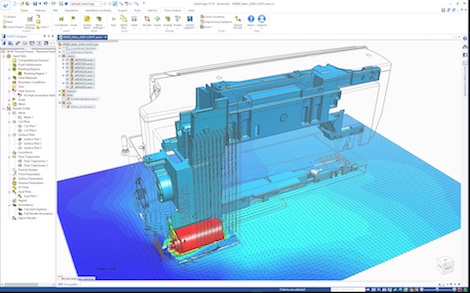
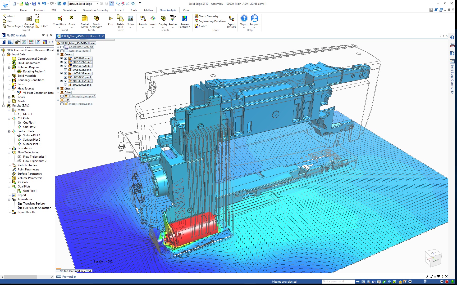
The add-on, FloEFD, lets users conduct fluid flow simulations within Solid Edge models – whether that’s internal fluid flow studies or more thermal planning studies around the interior of a product.
The current release looks well thought out and brings a set of tools to Solid Edge that, with the acquisition, are only going to become more intelligent and more productive.
We’ll be taking a deeper look at these updates and others made in Solid Edge ST10 in the July/August issue of DEVELOP3D.
In the meantime, you might find it interesting to watch the man behind Solid Edge’s development, Dan Staples, give his talk at DEVELOP3D Live this year.


