
The Peel 2 CAD-S is a scanning device that boasts a sharp focus on capturing smaller objects in finer detail than its predecessor, the Peel 2. It’s a welcome addition to the Peel 3D product range, as Al Dean reports
Back in the April 2019 issue of DEVELOP3D, we took a look at the Peel 2 CAD 3D scanner from Peel 3D. As we noted at that time, the brand is an offshoot from Ametek/Creaform. It takes all of the parent company’s 3D scanning knowledge and reverse engineering, and then wraps it up into more affordable products, under a different brand name, to attract a different audience.
When we looked at the Peel 2, we found a scanner that was capable and useful in many contexts, but that lacked the ability to capture finer details on parts. This time, we’re taking a look at the newer Peel 2 CAD-S, to see what’s changed.
The Peel 2 CAD-S takes much the same approach as its predecessor in its use of structured white light, but it dials down the resolution, so it’s better suited to capturing finer details. To give you the numbers, the Peel 2 CAD-S focuses on a recommended part size of under 0.5 metres, compared to the 0.3 to 3m recommended for the Peel 2.
What this means in practical terms is that, using the same sensors and camera rig, the size of the projected image shrinks from 380 x 380mm to 142 x 108mm. Essentially, you’ve got the same number of pixels in a much smaller space, so the Peel 2 CAD-S can capture 3D forms at a mesh resolution of 0.1mm (or, in other words, a fifth of the resolution that the Peel 2 offers).
Peel 2 CAD-S – Set-up and first use
The set-up process is much the same as almost every other 3D scanning unit. All of your kit is supplied in the usual foam-lined pelicase: the scanner unit, USB software and licence dongle, and the cabling. This cabling combines power (in a standard power brick) and data (via high-speed USB 2.0). Installation is a snap. Pop in the USB, start the install and you’re guided through the process.
In terms of hardware requirements, you’ll need a modern workstation/laptop with a 2GB Nvidia GPU in place as a minimum. The faster the better, but as the system is targeting smaller parts, the odds of maxing out a modern GPU are minimal.
Once installed, it’s time to break out the calibration plate. Calibration of these types of units is simple and the general advice is that it needs to be done semi-regularly, but in particular, when the conditions in which the device is used changes. That could be in terms of ambient light (such as moving to another office or another area of the shopfloor/workshop) or of temperature. With calibration completed, you’re ready to go.
When first firing up the Peel 3D software, you’re presented with two basic pathways. If you want, you can follow a guided workflow, which takes you through the scanning process, defining how you want to capture your object, the resolutions used and the tracking methods (such as geometry, textures and registration markets), and gets you working. The other pathway is to perform the set-up yourself and crack on.
Essentially, you need to first define the resolution of the scan. It’s set at 1.0mm by default, but the scanner can work from 0.1mm up to 2.0mm. The smaller the number and finer the resolution, the more dense the scan and the larger the dataset. Given that the Peel 2 CAD-S scanner is built for capturing smaller objects in finer detail, if you’ve got a decent GPU on board, you shouldn’t have any issues running at 0.1mm.
The next step is to set how the system tracks the movement of your scanner around your object. As with many such devices, you have three options here: texture, geometry and marker. If you’ve read our 3D scanner reviews before, you’ll know that structured light scanners enabled with texture capture are able to use surface texture to also track movement of your scanner/ object. The Peel 2 CAD-S can also use the geometry of your object. Both of these approaches are highly suited to organic shapes and textured objects.
If you have more regularly shaped parts with uniform surfaces (most commonly associated with mechanical parts), then you may need to employ registration markers.
These are small, known-size reflective markers that can be stuck on or around the object. They’re used to triangulate the position of the scanner in relation to the object. As long as the scanner can see three markers at any one time, this approach usually delivers a good result and keeps the scanner tracking properly.
The Peel 2 CAD-S is also supplied with a set of small plastic devices that feature three markers and these can be placed around your object for very quick set-up. This is particularly useful given that the scanner is focused on scanning smaller, higher detail parts, and sticking a series of 4mm stickers all over them isn’t likely to lead to success.
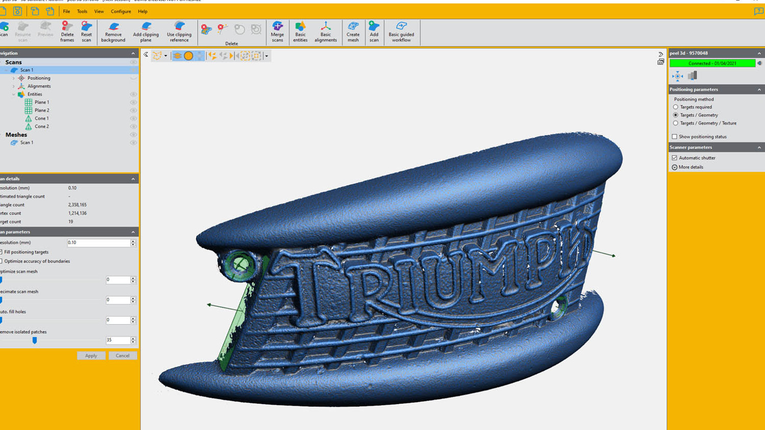
Peel 2 CAD-S – Scan process
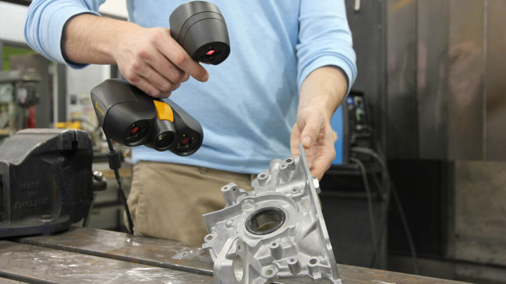
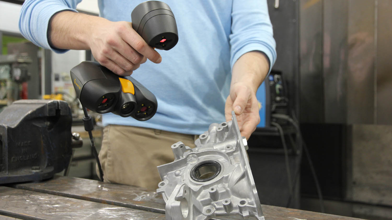
The scan process, as is common, involves you capturing as much data as possible in a single orientation. The device is pretty lightweight and nicely balanced (a boast that many competing products can’t make.) The combination of on-screen range finding (the ideal is 300mm from the object) and on-device lights mean that you can very quickly scan the part in front of you.
It’s worth noting that the Peel 3D software presents you with a very rough preview. Since the device is typically capturing a huge amount of data, filtering that back incrementally as you work makes sense.
As you get used to how the device works and how quickly you can move the scanner around your object (or how quickly the part turns on a turntable), you’ll also learn how to maintain tracking. At any point, you can take your finger off the trigger, pause the scan and inspect the data, then go back to scanning missed areas.
Once that initial scan is done, you have two options. If you have enough data, then you can start the clean-up process and remove the data you don’t need. There are a number of tools to achieve this and the workflow is pretty slick – one of the areas where all that Creaform know-how pays dividends. You then take it through a meshing and further clean-up routines.
The other option, particularly when you’re working on more complex parts and need a more comprehensive scan, is adding another scan set. This repeats the same process, with the end result being two or more scan sets that need to be registered together (unless you get really lucky). Again, Creaform’s knowledge and knowhow comes into play here and you can use common points (where you select three common points between the two scans or more) to integrate your scans.
Once you have your scan (or scan set) ready, the next stage is to prepare it for your downstream workflow. It might be the case that you simply want to mesh the points, perform some hole-filling and export your data as an OBJ or STL. In that case, the available tools will help you smooth surfaces, remove any noise and fill any holes, to arrive at a robust export.
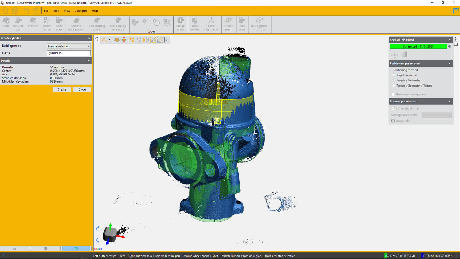
Alongside this, you may want to take your points/mesh data and construct analytic surfaces based on it, either as point of reference for reusing the mesh in a CAD system (the surfaces would allow you to align and assemble it in place), or to create reference geometry to build a fuller model.
The Peel 3D software isn’t really designed to let you build a fully enclosed solid model. Instead, its intention is to help build a set of reference surfaces that are fitted to the point and mesh data. From there, you can import them into a more complete 3D design system and complete your work there, based on references pulled from the scan data.
While this might sound a little complex, the reality is that, in most cases, a more prismatic part can have surfaces (such as cylinders, spheres, planes and so on) added in no time at all.
Once that’s done, those surfaces and points can then be loaded into your CAD system. This will typically require two export operations: Firstly, the mesh file as an STL or OBJ; secondly, the surfaces as a STEP or IGES (for instance) . This means you should end up with a set of two geometry types which can be used to build up the model as needed.
In conclusion
When we first looked at the Peel 2 scanner, it impressed us. The price was lower than has traditionally been the case; the build quality was excellent; and, just as importantly, the software was robust and easy to use. The main issue we had was that it wasn’t a good fit for those wanting to capture finer resolution scans.
What the Peel 2 CAD-S does is take the same approach as its predecessor, but focuses (both literally and metaphorically) on smaller objects and on capturing finer detail – but retaining the same ease of use combined with Creaform’s software.
The scans captured are outstanding in terms of detail and once you’ve mastered the art of multiple scans, registration and alignment, along with the practicalities of dealing with reflective surfaces, you can make some real progress.
The ultimate combination might be using both devices in a single office, giving you more options and the best of both worlds. In fact, there’s just such an option. If you’re in the market for 3D scanning capability, the Peel 3D product range is worthy of deeper investigation.


