NX 11 – Despite a 30 year heritage, Siemens NX is still finding room for innovation. We look at what’s coming in NX 11 and find topology optimisation, a new visualisation backbone and a hint at Parasolid’s future
How do you start with a system like Siemens NX? Its legacy stretches back to the 70s, through Unigraphics, the merger with I-DEAS and the subsequent revamp it’s been undergoing for the last couple of years in terms of usability.

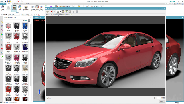
NX 11 sees the release of a new variant of its existing Ray Traced Studio module. This is now built on LightWork Design’s Iray renderer and gives you all that progressive, physically based visualisation goodness you’d expect
With the release of NX 11, Siemens PLM is still finding areas for innovation to enhance an already breathtakingly mature system.
Backbone updates
NX has been through a rework of its user experience in recent years. The result is a UI that is clean, fresh and clearly laid out.
While this hasn’t been tinkered with for this release, there are a few updates to the underlying architecture that apply to almost every user, so let’s take a look at those first.
The biggest area, something that NX users might already be aware of, is that the existing built in photo realistic rendering engine (or renderer, if you prefer) is being replaced with LightWorks’ Iray.
While the previously integrated tools were good, this takes things to the next level. All of the progressive, physically based rendering tools are now built into the system.
Iray (or the Iray+ variant) will use your CPU to compute the render but if you really want to make the thing sing, you’re looking at using an NVIDIA chipset.
With iRay+ you also get a bunch of new out of the box materials, all based on the open MDL format that LightWorks has developed. These materials allow you to define how the material will look in a layered approach.
So car paint, for example, includes the underlying surface metal, the paint, the flake and then the clear coat on top. This means that you can build materials that are realistic rather than a fudged approximation of what they should look like.
There is also the, now standard, set of HDR image-based environments for quicker and easier lighting set-ups. Again, this means that you’ve got a wide pool of both stock HDR images as well as tools like HDRLightStudio to help nail lighting in your renders.
Interestingly, with NX 11, Siemens is bringing out a cloud-based network renderer. This will be a no cost option from Siemens but will require a NVIDIA Iray Server from NVIDIA.
This means that you’ll be able to farm out renders across your network of workstations. There’s also talk of a cloud-based render service too, but it’s still early days for that.
A last note on the UI is that all of the tools mentioned above are built into the existing Ray Trace Studio module, which means that they will be available to all customers (the network renderer aside). With no limitation of the rendered output, you can render out those 4K images for presentations all day long if you wish.
Points and meshes
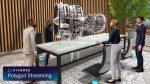
One of the core focuses for this release is the introduction of much greater support for working with point cloud and mesh-based data.
NX has had tools for dealing with meshes and converting them to surfaces, the traditional Reverse Engineering approach, for some time.
What the team at Parasolid (also owned by Siemens) have been working on is a solution to use the mesh models directly.
Whether that’s from scan or data capture processes or imported from other systems. This release changes all that but as we’ll discover, it’s only the starting point.
The first big change is that Siemens has licensed some of the PointTools technology from Bentley Systems. This means that point cloud data from large scale scans of buildings and factories can be imported and displayed efficiently inside NX.
Together with Siemens’ recent move to bring some elements of factory and production line design into NX (with Mechatronics Designers last year), this makes for a huge system.
With the datasets from such scans being in the order of Gb if not Tb of data, the system will load .pod files from PointTools, display them (with texture if captured), and use them to build around — even allowing you to snap to the ‘geometry’ when needed.
But that’s not all Siemens has up its sleeve for dealing with reality captured data.
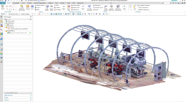
Siemens has licensed Bentley Systems’ PointTools technology to allow importing of large scale scan data sets for factory layout
NX 11 – convergent modelling
A good eight years ago, Siemens kicked off something that had long been dormant in the 3D design and engineering software world.
With the release of Synchronous Technology, the company brought to the fore the idea that direct modelling, which was by no means a new idea, could coexist with the more traditional and widely accepted means of building 3D models.
It was implemented into both of its products — NX and Solid Edge — and has since seen most other vendors take elements and ideas into their own toolsets.
For NX 11, Siemens is introducing the ability to mix solid and surface modelling methodology with mesh or polygon based data. These capabilities are being implemented inside of the Parasolid kernel.
The idea, called Convergent modelling, means you can bring polygon data into your NX models and use that as you would more traditional parasolid features.
This modelling tool has been introduced into NX 11 but it’ll also be made available to other licensees of Parasolid should they choose to take it on.
Being the first time it’s been incorporated into a Siemens product, it’s interesting to note how it differs from simply importing and converting a part to a NURBS model. What’s intriguing is how the mesh data looks to be integrated into the modelling process and feature history without the need to convert it to a b-rep model first.
In NX you can trim, Boolean, scale, mirror (the list goes on and on). The caveat in NX 11 is that the result will be a parametric facet body.
In NX you can create traditional feature models and have convergent models and operations between them with the output always being facet, but feature based, parametric facets.
At present, the workflow dictates those features that become ‘convergent’ and they immediately become self limiting in terms of what you can do downstream.
To explain that a little, it’s perfectly possible to bring in medical scan data and use it in combination with more ‘engineering’ type features to build fixtures for implant or surgical guides, for example.
But as soon as you do, you’re limiting what can be done. So the modelling workflow needs to be thought out in advance.
Currently, there are some limitations on the downstream features that can be created so I’d imagine folks looking to take advantage of these tools would make use of multi-body modelling approaches and only bring the bodies together at the last minute.
It’s also worth noting that, at the moment, the associativity is limited. So although you can replace the originating mesh, importing the new STL geometry and reparenting it is a bit of a convoluted workflow but it can be done.
With this first release of Convergent Modeling you can take the models into the NX CAM and CAE tools but Siemens recognises that there are improvements that need to be made to optimise that process and to support the full range of downstream capabilities.
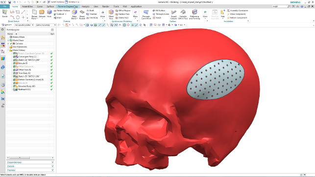
NX is the first implementation of Parasolid’s new Convergent modelling approach that will allow you to work with mesh data directly alongside and integrated with your more traditional solids and surfaces
Topology optimisation
In terms of technology for design and engineering, it seems that topology optimisation is gaining awareness with more activity around the subject than there has been in the last 20 years.
Much of this drive has been from the interest in additive manufacturing, but to say that this is the key application for it would be wrong.
The ability to gain guidance as to the best structure to solve a particular set of engineering performance criteria is incredibly beneficial. And while topology optimisation has historically been something conducted separately from the workhorse CAD system (such as SolidThinking Inspire), this is now changing.
Interestingly, Siemens is starting to build such tools into NX based on the technology from NYC-based startup, Frustum.
The new NX Topology Optimisation module follows an expected workflow for these types of things. You define your design space, in terms of features that need to be maintained, a geometry area that will become the focus of the optimisation (shown in the image below as transparent pink), any keep out areas (in yellow in the same image), then define the boundary conditions in terms of loads, constraints, materials and such.
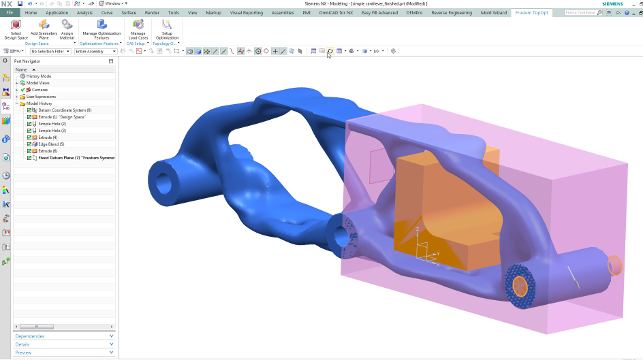
Siemens has licenced Frustum’s topology optimisation tools to bring such tools directly inside NX
Finally, you then define the parameters for the optimisation process, as a mass target (that’s why you define a material rather than using a percentage reduction).
You can also define any areas of symmetry (the image above has one) and then, finally, the speed/resolution of the process.
The end results are what we’ve come to expect from topology optimisation these days — a mesh that’s organic in shape and which provides the idealised structure to solve the given design challenge.
What’s interesting is that we’re now starting to see the next generation of these types of tools.
While Frustum’s tools provide a much cleaner surface, other tools such as solidThinking handle it differently but the end results are similar, as you’ll learn later on in the magazine.
When combined with the new convergence modelling tools, you’ve got a fascinating environment for design and development of additively manufactured components that are incredibly lightweight.
However, that said, there’s also, of course, huge potential for using these types of tools to guide the design of more traditionally manufactured components as well. Although it’ll be a slightly more convoluted process to take that mesh and use it as reference to build a more traditional model that can be cast, machined and/or moulded.
NX 11 – Flattening & forming
The last few releases of NX have introduced a range of industry specific tools, particularly in aerospace.
Rib and stringer design was the focus for the NX 10 release. This continues in NX 11 with some work being done on joggles where stringers meet ribs and, in particular, adding flanged cutout to ribs.
This release also features flattening and forming related tools that are focussed specifically on double curvature forms — regardless of manufacturing method or material used, e.g. can be fabric or plastic or metal.
For some time NX’s flattening tools have enabled users to take a complex surface or set of surfaces and flatten them out for blank development etc. But these were built on a pretty heavy CAE based approach so the Siemens team set out to create a designer level tool.
The new set of flattening tools eschew this CAE, finite element approach, it uses a non-material based minimum deformation approach to flattening. This gives you almost exactly the same result but in a fraction of the time. We’re talking seconds rather than hours to set up.
To use it, you select the surface or surfaces you want to flatten, pick the point in space to flatten to, pick a primary direction and — pop! — you’re done.
There are then tools that allow you to conduct some analysis, such as distortion mapping that shows where pinch points or tears might occur.
What’s also interesting is that some additional features have been built on top of this new approach. For example, you can now add in another sketch to the flattened form (perhaps for a cut out, to add strengthening features or additional fibre lies) and have that automatically reflected back into the original formed model.
This is also complimented with the new tools that allow you to project a 3D sketch onto a surface (to cut out a feature) and have the cut maintain the surface it is cutting (rather than projecting from a single plane vector) — think cutting features for windows or other inlets/outlets in a fuselage.
NX 11 extends the rib design tools into sheet metal design — Flange cut out (applied to flat pattern) and Lightening Cut out (flange with stiffening flanges to specified angle). You can also build a plane to reference surfaces — to outer mould line (OML and IML).
Finally, it’s also worth mentioning that there’s been some reconfiguration of the product offerings. You’ll now find that all of the aerospace sheet metal related tools are being rolled into the advanced sheet metal module meaning that all those tools will be in one place, rather than two separate cost options.
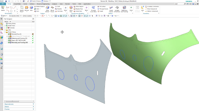
NX 11’s new non CAE based rapid tools for flattening complex surfaces
NX 11 – variable offsets
It’s not often that we highlight a single new feature in a design system, but this one struck me as being worth the effort as it shows how intelligent these mature systems are becoming and how hard the users are pushing development.
So, let’s take a look at Variable offsets.
Consider taking a single set of surfaces like those found on the outer skin of a car door. Then consider the matching internal surface that’s welded to it.
That internal skin is very different. It has strengthening features that are required to reduce the weight (or lightweighting as it’s commonly referred to) as well as all manner of other features to provide access and mounting positioning for the various hardware and
panels.
Designing that inner surface is a complex business and is typically defined in terms of offsets from a single surface outer. The new variable offset operation in NX 11 allows you to create the basic forms and offsets, in specific regions, in a single feature.
Take a look at the image below.
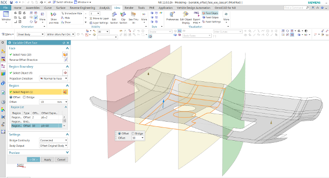
The new Variable offset tools create complex, lightweight structures from a single set of surfaces
This shows how a single surface can be adapted to create not only a uniform offset from it, but also how features can be added in to provide strength where needed.
You have full control over the process — the offset values and how the system builds the transitions between each offset — all driven intelligently from a single feature and a single sketch.
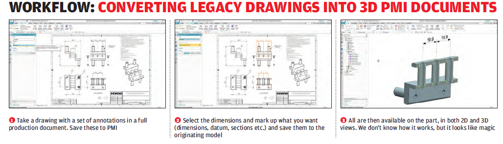
NX 11 – 3D drawings & PMI
The final update we’re going to talk about for NX 11 relates not to modelling or drawing creation, but rather a combination of the two.
PMI (Product Manufacturing Information) or 3D annotation is a topic that has been bubbling away for a good few years now.
Some industries have ignored it while others have taken it on board.
Part of the issue is that in many cases you’re creating the MPI directly on the model, then pulling that information into a 2D drawing. Very rarely is it done the other way round.
That makes sense when you’re creating data from scratch, but if you’ve got years, if not decades, worth of legacy data, the process of taking that vital GD&T (Geometric Dimensioning and Tolerancing) back into your 3D model is both time consuming and painful.
To get around this, NX 11 allows you to have a product model with associated drawings and the key GD&T, but then uses some clever tech to apply that drawing based information back to the 3D model.
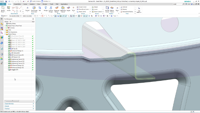
The new aerospace design tools have been expanded in terms of capability, but also simplified in how they’re packaged
In conclusion
Whenever I sit down to write about NX, it’s always difficult.
The system is one of the true legends in the 3D design and engineering industry and while it’s now over ten years old in its current form, it has a legacy that stretches back to I-DEAS and Unigraphics in the 70s.
That legacy shows, both in the breadth of the system’s capability, but also in the customers that use it. It’s capable of designing some of the world’s most complex products and does things that most other design tools still can’t even touch.
But, despite its maturity, in each release there’s a vein of innovation that runs through it. Highlights for this release have to be the introduction of the Convergent modelling methodology that’s built into Parasolid, which Siemens owns and develops.
While the ability to work with meshes alongside solids and surfaces isn’t a new concept and some systems have been doing it for years (if not decades), its introduction into a mainstream tool like NX shows what’s possible, even at this early stage.
Other highlights include the introduction of topology optimisation — something that more and more folks are becoming interested in. The interest has been driven by the increase in awareness and acceptance of metals-based 3D printing, but it’s by no means limited to that area.
| Product | NX 11 |
|---|---|
| Company name | Siemens |
| Price | n/a |