Al Dean catches up with the system that closes the loop when parts start rolling off the shop-floor
As we’ve discussed more times than I’d like to recount, Delcam’s product range has an all-encompassing coverage of the design to production process. From the likes of CopyCAD, through PowerShape and ArtCAM, into PowerMill, FeatureCAM and others for machining, Delcam covers all the bases unlike almost any other software vendor.
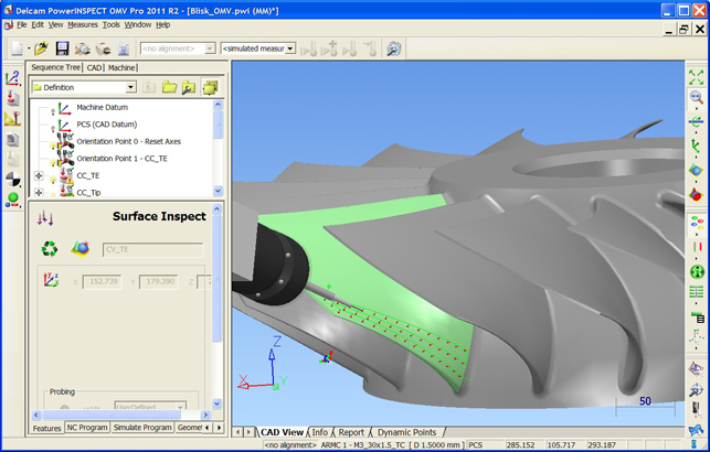
Here points from the UV curves of a surface are used to define an inspection path for touch probing
But alongside those tools, the company has another ace up its sleeve in the form of PowerINSPECT. As you may guess from the name, this focuses on the inspection and quality assurance process. The short version is that it allows the loading of the nominal CAD geometry of the part, then assesses and reports on the variance of the manufactured part from that nominal. The longer version goes a little bit like this…
Importing the nominal
The first step is to load up the geometry of the part. PowerINSPECT takes advantage of Delcam’s translation tools and can read pretty much every format currently in use, from standard formats like STEP and IGES to a formidable slew of native formats. This includes the likes of Catia, NX, Pro/Engineer, SolidWorks, as well as Parasolid and ACIS data.
In the latest release, the system can also read in 3D annotations (in terms of GD & T data) from Catia and NX native data. It’s worth noting that, at present, it can’t read the same information from JT data. According to the company, while there’s a great noise about JT, it doesn’t see much use of it on the shop floor by Delcam customers as they typically have the native data to work with.
Inspection process and hardware support
The next stage is to define the inspection routine. The exact details of this will depend on two key factors. Of course, there are the main attributes that define the geometric features and associated tolerances that the user is looking to maintain. Datums, specific geometric and measurement tolerances can be setup with ease from a pretty stripped back user interface.

Alongside these established and well known factors, the other key thing to consider is the inspection hardware in use. While the Co-ordinate Measuring Machine (CMM) has been seen as the zenith of metrology, and PowerINSPECT supports both manual and CNC driven metrology, there are now a host of other options. The introduction of these onto the shop floor inspection environment has driven much of PowerINSPECT’s development. So, let’s explore these in some detail.
Non-contact scanners: The use of non-contact scanning devices as a means for part inspection is growing. Both laser and white-light scanners hold several advantages over contact-based inspection.
Firstly, the amount of part data that can be captured in a relatively comparable space of time to traditional methods is dramatically greater – and it is more holistic in its nature.
While traditional probe-based inspection excels at measuring discrete points on a part, it’s limited by its nature to those points. Also the amount of measurement that can be done in between those key points has a linear relationship to the time it takes – more measurements mean a longer inspection cycle.
Conversely, with a scanning device, it’s possible to scan the entire part and gain insight into the nature of the manufactured item. Laser scanners and the like will capture millions of points in the same time that a CMM takes to move between reference measurements. As a result, insight into the whole part can be gained. Of course, traditional measurement techniques have advantages over these methods.
Portable measurement: Consider the concept of a metrology department and what do you see? White lab coats, a granite base CMM and a lot of waiting. The problem with CMMs is that they are fixed in space by their very nature. Essentially, the parts need to come into the quality department for inspection. If the parts are portable, then this isn’t a huge issue. But if a pallet truck or even a crane is needed, then it’s clear that there might be a more efficient process. It’s here that portable measurement devices excel.
Today there is a booming industry engaged in developing measurement devices that can be used on the shop floor to inspect parts in-situ. There are measuring arms (from the likes of Faro or Romer) with either ruby tipped probes or laser scanning heads attached. There are arm-free handheld scanners (such as a Creaform), camera tracked hard probes (such as Metronor or AICON) or measurement probes (from suppliers such as Renishaw) fitted into a CNC machine tool. The idea of having to move parts to the inspection equipment is rapidly becoming non-standard practice in many organisations.
Integrating diversity into inspection
PowerINSPECT supports all of these methods allowing the user to define inspection processes that take advantage of all of the hardware at their disposal.

During the initial set-up process, not only does the system define the standard geometric and GD&T measurements, it also defines point measurements where the difference between the nominal and the holistic scan can be reported upon.
Basically, the initial inspection is conducted, either using a scan, hard probes or CMM style inspection methods. The system then records and wraps these up into a reusable inspection method that can be deployed where needed. It will then handle the loading of the relevant part file, alignment of the scan to the nominal and guide the operator through the process – whether that’s conducting the scan or taking hard measurements. So, it’s clearly defined and ready to go once the inspection is completed.
Reporting and documentation
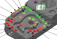
The reporting tools within PowerINSPECT are designed to be as efficient as possible. They allow the capture of all those measurements taken (irrespective of method) and present them in a clear manner that documents the variation of the part from the ideal, where measurements are in or out of tolerance using point callouts with full data presented on screen.
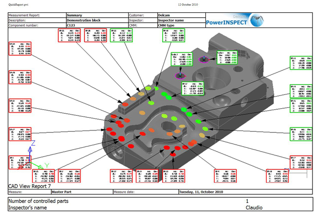
If the user is dealing with holistic scanning, the reports will show a shaded map of exactly how the manufactured part differs from that ideal and again, discrete points can be pulled out and documented in specific detail. The 2011 release also introduces a quick one page report with a graphical image, header and footer for those that are looking for a quick summary rather than a complete inspection report.
Conclusion
The world of metrology and inspection is changing, and changing rapidly. Traditional hard probe systems are advancing onwards from the CMM and learning lessons from the portable devices out there. The primary reason is that for all their sci-fi laser based goodness – and who doesn’t like anything involving lasers? – they still suck at some of the key things.
Anything involving a sharp edge is difficult to scan and that’s why you will typically need a combination of the two for many tasks. CMMs will never disappear either and for those key critical inspection tasks, there are no substitutes. That said, portable and non-contact devices are gaining ground in terms of accuracy.
So, with everything in a state of flux, what about the software system that drives the use of these devices? PowerINSPECT has a well established position in the market. It not only provides all the required tools but also brings some unique things to the table. Its cross hardware platform allows for a mix and match, not only of measurement hardware in terms of method, but also of hardware itself.
While many large organisations will standardise on a single hardware vendor, many smaller organisations typically have a wider spread of tools built up over time depending on use and budget. The advantage of PowerINSPECT is that inspection routines can be deployed across any set of devices and used by almost anyone. Of course, that also reduces the need for training.
www.delcam.com
On machine verification and software fixturing
This is something I got to see first hand in Delcam’s own tool-room. Consider the machining of something large and geometrically complex, whether that’s an injection mould tool, a stamping die or indeed, a single piece of boy racer alloy, which is the example we worked through. What connects these types of products? Firstly, they’re complex shapes with very few straight sides or points of reference. Secondly, they’re bloody heavy.
That combination makes life a misery for those having to set-up the components on the bed of a machine tool. Whether a machining job is being inspected half way through or you’re looking to set a complex casting or remachine a complex component, taking the part off the machine tool bed means headaches of epic proportions.
Here Delcam has two key technologies that can help and both use a measurement probe that fits into the tool-holder of a machine tool. The first, On Machine Verification allows inspection to be carried out midway through a machine job. It enables the user to sanity check their work before continuing. The second, Software Fixturing, is fascinating.
Basically, the same type of device is used to measure the actual position of the part on the machine bed. Those measurements are applied as a transformation to the tool-paths on the controller and, hey presto, the tool-path matches the part. No messing, no big rubber mallet and no skinned knuckles.
Of course, the system requires the user to accurately and repeatably measure a known artifact so that the measurements are sure to be accurate. But for those working with complex shapes, this holds huge set-up time savings.
powerINSPECT 2011
Delcam
On application
Delcam’s product range now covers the gamut of art to part.
No