

In this article, the second in the series of simulation workshops, Laurence Marks looks at the modelling of an impact scenario
Impacts have traditionally been the domain of explicit solvers and in this workshop we look at how the explicit solver approach differs from the more widely used implicit technique, and how this can be used to solve a typical impact problem.
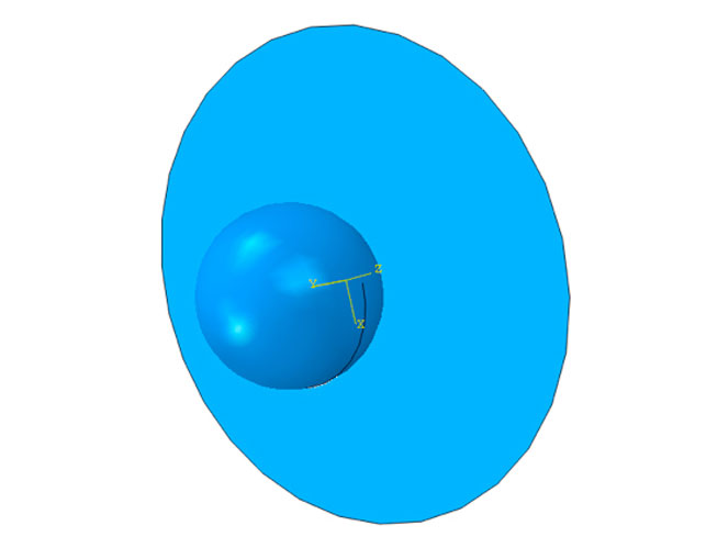
Simple geometry used, in this case generated in a CAD program; but could have been generated in the FEA system
Once we’ve looked at a new solver approach we can investigate how it can be harnessed to do some impressive things with material failure.
Geometry
As with all these workshop examples the geometry is relatively simple – the interest comes from the complex behaviour.
The ball is modelled as solid, unsurprisingly, whilst the plate is represented as a surface. This surface will be meshed using shell elements – a technique that allows us to specify that an object is made of 3mm thick aluminium rather than just aluminium.
Meshing
Very little to say here… and so much. So, let’s just say that the ball is meshed using lower order tetrahedral elements and the plate using lower order shell elements – mesh density has surprising and critical effects on the solution.
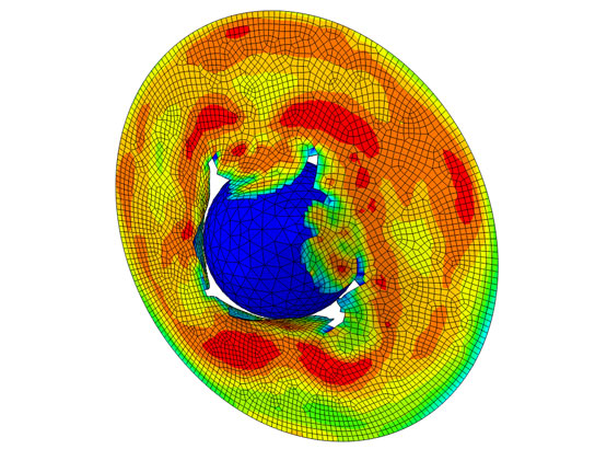
In this model the steel ball impacts an aluminium plate, a simple scenario made more complex by allowing the material to fail, which lets the ball pass through the plate
Model set-up
This is pretty simple for a finite element model – contact uses a catch all general contact approach, the edges of the plate are fully restrained and the ball is given an initial velocity.
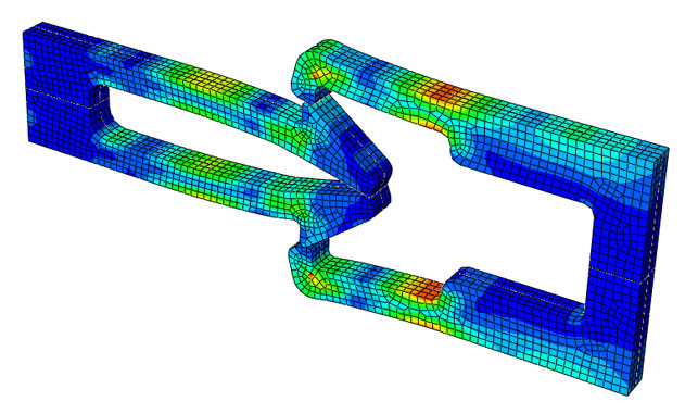
Some seemingly simple components, such as snap fits, can be very tricky to model using a standard finite element program; explicit solutions make these fairly routine
Explicit solvers
Many readers will be familiar with the concept of a finite element model being a collection of spring stiffnesses that represent a structure, and the controlling physics being Hooke’s Law.
If you pull a spring it gets longer. But an explicit solver works by dividing the structure into masses. If you know the forces acting on a mass you can tell, using a law of Isaac Newton’s, where it goes and how quickly.
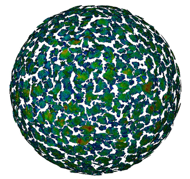
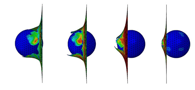
This model of a sphere with an increasing internal pressure shows what happens when the stress in many of the elements goes beyond the critical level
Those forces could either result from inertia, be externally applied, or result from the fact that you’ve connected one mass to another with a spring. Simple really. It’s also rather ironic that the two great ‘Geniuses of British Physics’, Hooke and Newton, who hated each other with a passion, have had their work coded together in a CAE solver.
Why explicit?
Explicit solvers have advantages in some situations, the traditional implicit solver has advantages in others. Explicit solvers are great where the dynamics of events tend to dominate the other things that are going on.
So things like crashes, impacts, and forming processes all fall into that category. This different approach to solving the problem allows you to do some clever things. For reasons concerning solution stability, that I won’t go into now, you can allow bits to break off the model.
Recently explicit solvers have seen an expansion in usage as they are applied to interesting problems beyond the traditional realms. As with everything in the world of simulation, approaches and techniques developed in aerospace and automotive trickle down to the everyday design processes eventually.
Element size and solution speed
For various reasons the number of time steps used in an explicit solution is generally quite large, and the controlling factors are the shortest element edge length in the whole model, the density and the modulus.
Frames from the animation of the results show how the plate progressively fails allowing the ball the pass through the plate
Basically a shock wave can’t cross an element in a single time step without causing trouble. For this reason analysts pay close attention to element size, it’s often the difference between success and failure.
Damage and failure modelling
If we are going to let bits to break off a model we need some form of physics based rule for allowing this to happen. So, in the model shown we’ve told it to delete elements in the plate when they reach a critical level of deformation.
And if you do that cracks and tears appear in the model. There are pros and cons to this approach and we’ll be looking at more exotic approaches for crack propagation in later workshops.
What the model shows
We can track pretty much everything in this model. Deflections, stresses, strains, velocities, accelerations are all up for grabs, as is the way in which material failure progresses through the plate.
The solution shown took minutes to solve on a four processor PC running Abaqus. Again an impressive FEA solution has been achieved in a sensible time frame.


