
Last month we looked at the updates to the modelling and injection mould filling analysis tools — those geared up for mould design.

Wire EDM – support for slug retention grooves which are particularly useful for press tool apertures
We found a mature system that is now placing a big emphasis on enhancing the user experience. So shall we take a look at what’s new in the manufacturing aspects of Vero’s VISI?
VISI PEPS-Wire
When Vero acquired Camtek, it began the process of building Camtek’s impressive Wire EDM (Electro-Discharge Manufacturing) tools into its VISI product suite.
While the first version of VISI PEPSWire was all about cramming the tools into the same user interface, this second release starts to focus more on adding in the additional CAD-related tools to help generate actual geometry for wire EDM.
There’s been a lot of work done on the CAD side to help generate wire profiles. As ever, this means a focus on offset profile creation. While the system has had these types of tools for years, there are now greater options for filling offset gaps in complex profiles (which may break the geometry and create multiple islands) with circular arc, tangent or curve-led extension.
It will even trim and close the profile to ensure you have robust geometry from which to drive your CAM operations.
In terms of more wire operationfocussed updates, the big news for this release is feature recognition support for variable land and taper (collar) operations.
Elsewhere, there are new automated tools to create retention slugs at predefined points around an aperture. These slug retention grooves are particularly useful for press tool die apertures where ‘slug
pulling’ can sometimes be problematic.
There are some new tools to assist with wire-based transformations (such as move, scale and copy) that allow you to grab a tool-path and move/rotate/copy it into a new position, but retain the link back to the original.
While this might sound odd, if your part has multiple instances of the same feature, the ability to edit the master and roll-out these changes to the other features is highly productive.
If you use Charmilles Technologies CT Expert, found on the Charmilles, Millennium and Fanuc controls, you can activate it from VISI directly and load specific technology from this application in the form of offsets, power settings, feed rates and such directly into the operation dialog.
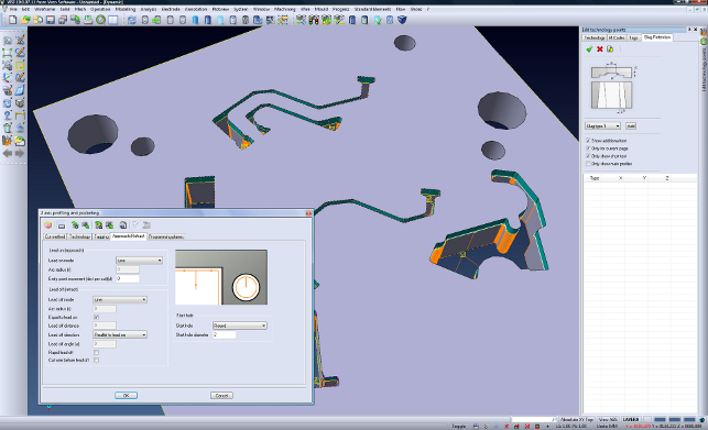
Finally, there’s a new Autopoint tool. This will automatically add a pre-drilled point to specific aperture geometry (such as a pre defined offset from the longest length, or the aperture centre points) and use them as the default approach point when adding machining operations.
VISI machining
Moving onto more traditional CNC programming, the big new feature is that all CAM functions (3, 5 axis and the simulation tools) are capable of running on 64-bit Windows.
This is excellent news for those working with huge datasets and highly complex operations that might have previously hit the memory limits of a 32-bit operating system. Looking at the software in more detail, there are now four new CAM strategies.
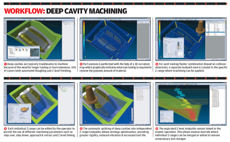
The first is aimed at the machining of deep cavities, with both roughing and Z level finishing covered. Geometry is selected and the system runs a 3D curvature analysis to highlight the smallest radius. VISI then provides a read out that shows where the radius varies – to help with cutter selection.
Once chosen, a safety clearance and tool length is added, the system then shows where the current tooling set-up can reach. By selecting different tooling combinations/extensions, the operator is able to automatically split the cavity into multiple Z depths based on collision detection.
Each individual Z range can use different machining parameters providing greater rigidity, reduced vibration and increased tool life. This optimises a process that is typically based on guesswork when dealing with very deep and complex pockets.
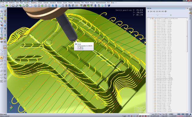
Another new strategy is the Hybrid Constant Z, which is very similar to the existing steep and shallow concept that combines a couple of operations into one, that will machine both steep and shallow areas in a single hit.
The main difference here is that the Hybrid Constant Z strategy uses a 2D pocketing projection for the intermediate planar areas instead of a true 3D step over which dramatically reduces toolpath calculation time.
A new Core Roughing strategy has been developed with an improved toolpath shape when working from outside a component. The new tool-path will dramatically reduce the number of rapid movements, allow more than 50% step over of the flat area of the cutter and improve calculation time.
The result is a flowing toolpath that allows the machine to run near to its maximum potential when machining core components.
The final strategy is focussed specifically on the cutting of ribs and other thin walled components. The operation works with both roughing and finishing routines.
The standard approach of using multiple operations run the risk of damaging the component (often exotic materials such as titanium for aerospace), specifically towards the end of the process when the rib is subjected to high frequency vibrations and micro-flexes.
To overcome these problems the Rib Machining combines both roughing and finishing strategies to completely machine each level individually working down the model.
Other machining updates include the ability to re-distribute the toolpaths points set to reduce jerky movements and allow modern machine tools to reach higher programmed feed rates (Roeders machines
for example).
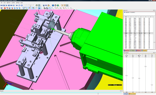
Another is that alongside its adoption of 64-bit computing, the machine tool simulation tools have been revamped. This is in both appearance and the amount of information you’re given.
The system now gives ‘time-based’ simulations so you can accurately move to a specific time window in the operation and see exactly where the toolpath is at.
Conclusion
From our look at VISI 19 over the past two months it is clear that Vero is pushing VISI into the business end of design and manufacturing.
Having been brought up and developed in the world of mould and die design the VISI team has a perspective that differs from that of the mainstream vendors.
In terms of 3D geometry wrangling, many mainstream vendors talk about how they handle complex geometry, and while they can create such forms, they simply won’t cut the mustard for those in the mould and die industry.
Often when a client sends data, that’s all you have to work with. There’s no going back and asking for a different format. Take it, fix it, prepare the core/cavity, the mould base and cut it. Job done.
In such situations, the geometry tools within VISI are first class. That competitive environment means that the tools let you work with problematic geometry and get it into a state ready to machine – never mind the perfect geometry of demonstrations and marketing documents.
Then when you look outside of design, there’s a whole host of new technologies being introduced with each release. New operations and options for machining cycles are added. The integration of flow analysis into the user interface is again another huge benefit to those preparing manufacturing component stacks.
And the work done to bring the wealth of knowledge from PEPS into the system broadens out an already extensive product portfolio that covers all the machining/CNC bases.
All in all, if you’re at the business end of manufacturing, where time and costs are tight, a system like VISI should be considered as part of your key toolkit.
| Product | VISI Series 19 |
|---|---|
| Company name | Vero Software |
| Price | on application |


