
Siemens PLM Software’s NX has led an interesting life since the merger of Unigraphics and I-deas some years back. The product assumed the natural role of the company’s flagship 3D product modelling system, it took over from Unigraphics as one of the most important products in the machining world and, since the introduction of NX Nastran, has also delivered some seriously bulletproof simulation and analysis tools.

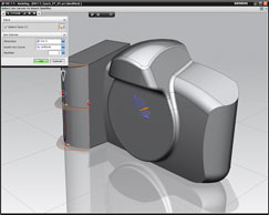
The new Freeform tools with Synchronous Technology allow users to manipulate not only prismatic geometry, but to also work freely with complex freeform, geometry
Along this journey NX has been through some serious rework, on both the underlying architecture and the user experience. The end result is a thoroughly modern system that’s not only applicable to a huge cross section of industry sectors, but is available on multiple platforms – it’s one of the few 3D systems to support Mac OS X and Linux. This month saw the launch of the latest release, NX 7.5, following on from the 7.0 release in October 2009. So without further ado, let’s dig in.
Lightweight data and performance
Before we get into the exciting modelling and product development updates, it’s worth a quick look at what has been going on under the hood. Siemens develops the JT format, which has seen widespread adoption in the automotive industry as a format for sharing data. It has also been used inside NX to display models in a lightweight format making it easier to load up large models on a standard desktop workstation.
Previously, in order to take advantage of the technology inside NX the user needed to specifically create JT-variants of full geometry. Now the system generates the JT-style data on the fly and as a product model is opened it loads the lightweight representation as default. This means that dramatically larger datasets can be opened and worked on in a much shorter time frame.
As with all such technologies, there will always come a point when the complete description needs to be loaded up, but with each release this point is being pushed further away. With NX 7.5 users can load, view, cross section/measure, create reference geometry from, and carry out parametric part updates, all without having to load the full heavy description of the data. While this won’t have a huge impact on those working with smaller assemblies, for those who deal with 10,000s of parts, it’ll make life much more tolerable.
Sketching efficiency
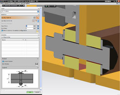
The new ‘component first’ concept introduced into fastener placement sees the focus shift from hole then part placement to one in which the user defines the fastener stack and the system generates the correct mounting features
The entire sketching user interface has been streamlined to make it easier to get from an initial idea to a feature and model. For example, now the user does not need to exit a sketch before building the geometry – he or she simply sketches, performs the 3D operation and it’s done. In addition, the sketching process is much more fluid than in previous releases and dimensioning is automatic. This allows the user to work with key inputs directly and to formalise geometry where needed. It’s interesting to note that these dimensions aren’t constraints as such. In order for them to drive as parameters they need to be added manually, but this should mean that precise geometry can be got down on “paper” as quickly as possible.
NX can now work with regions within sketches, so the need to create a fully trimmed boundary is removed, which makes things much quicker. Another speed enhancement comes in the form of the new NX Reuse Library, which lets users store profiles and sketch geometry, then quickly drag them out of the library and position them very quickly indeed.
Synchronous Technology
For those still unfamiliar with Sync Tech, this was a huge announcement from Siemens two years ago and it arguably kick-started the mainstream adoption of history-less modelling. While features remained a core part of the process, adding intelligence to models and edits and decreasing the system’s reliance on history was seen by many as the start of a new movement.
While a great emphasis was placed on the integration of Sync Tech into Siemens PLM’s Solid Edge product, NX also got a healthy set of tools that really took this approach to heart. Many industry pundits missed the updates made in NX, but this could be attributed to the fact that this wasn’t quite the revolution within NX that it was in Edge. NX had supported the freeform modification of geometry for some time and the changes were quite subtle. This was further compounded by the fact that the NX Sync Tech implementation allowed much more freedom to use the new modelling techniques as and when desired, either in a stored history method or not at all. Essentially it was integrated into the existing modelling workflow and user experience, rather than disrupting it completely.
In the first few releases, Sync Tech was applied to the creation and modification of prismatic geometry, allowing a combination of dynamically applied geometry filters and direct editing tools. For NX 7.5 this has been extended into the creation and modification of freeform shapes.
Sync Tech and surfaces
For many years NX has been able to work directly with surface geometry to a very fine degree. Rather than just relying on the traditional network of curves to construct surface geometry, it has allowed the user to dive in and control the form of surfaces in a much deeper manner, pushing and pulling CVs, isolines and such. This is the type of geometry editing that traditionally separates ‘solid modelling’ systems from true surface modellers.
For the 7.5 release, these tools have been reworked with Synchronous Technology and allow users to implement them in a flexible manner, storing history and each modification as a separate feature, or to work truly freeform. The tools are built into two key operations.
Replace Face allows users to grab geometry from parts and sub-assemblies and quickly adapt it to a new use without too many concerns about part history
xForm has been in NX (and Unigraphics before it) for some time and uses a wireframe ‘cage’ around the surface to push and pull it into the required form. iForm is a new variant of this, but uses the control points and isolines in the surface directly. Both approaches are suitable for different tasks and their use is interchangeable. What’s really impressive is how these tools can now be used in combination with a range of intelligent modelling tools, such as symmetry or the Sync Tech driven Face Finder and Replace Face tools, to make modifications that are intelligently linked to its surrounding geometry. Also because it works in the “free from history constraints” way that all Sync Tech-based tools do, downstream features (such as fillets, shelled etc) remain live and previews show the effect on the whole part during edits, rather just the immediate effect of a change to a single surface.
Replace Face – the perfect Sync Tech tool
It’s not often that I obsess over a single feature in a modelling system, but I’ll make an exception here. While the direct editing, intelligent push and pull tools of Sync Tech are impressive, perhaps the most useful tool for a designer is the Replace Face command. In its most raw form, it allows users to take existing geometry and quickly adapt it to their new requirements and application. Grab the geometry, match the faces into the new position and you’re done.
The new version now includes the ‘With Offset’ option. This extends the tool and means complex geometry can now be brought in and the Replace Face can be used in combination with the Face Finder filters to adapt it to a new complex form. When combined with the new easier-to-use Reuse Library it makes huge sense.
Reuse library and Fasteners
Data Reuse is a big focus for this release. From the more efficient 2D profile library and positioning method, the whole system encourages users to not only reuse data, but makes it easier to create those assets. While the system comes with a good range of standard profiles and sections, it’s always handy to be able to create your own set of commonly used profiles, whether those are for locating features or profiles for building common features.
To create an item in the Reuse Library the user simply grabs the geometry (be it 2D or 3D), copies it into the clipboard (CTRL+C), pastes it into a new dialog, adds the required details (such as a preview image, locators for positioning) and it’s done.
Alongside this, there’s also some work being done to change the semantics of how users work with fasteners. In essence, instead of creating a hole in an assembly, then adding the fastener to it, the user creates the fastener in position and the sub-assembly stack (with hardware such as washers, spring clips etc) also creates the appropriate hole to support that feature. This could be a series of pass through holes or with a thread, for example. It’s a subtle change, but one which makes perfect sense – after all, what you want is two parts connected with an 8mm hex head screw and not an 8.1mm hole.
HD-3D
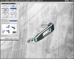
The enhancements made to HD3D, which bring clarity and richness to the often overwhelmingly complex and cryptic data we store in our data management system, are impressive
High Definition 3D (or HD-3D for short) was introduced last year with the NX 7.0 release. It combined Siemens’ experience in lightweight data visualisation (from the JT format) and Data Management (with Teamcenter) and created an environment in which users could graphically explore a product in development and discover all manner of information. This could be project status information, where supplier content was found, or where the various sub-systems were in terms of the project timeline.
These Visual Reports allowed users to add rich graphical context to what would previously be a text-based data management query. Alongside Visual Reports, the system was also used for Check Mate reports to discover whether or not parts or sub-assemblies adhered to all manner of geometry and topology-based standard checks (such as using the VDA geometry quality requirements) or internal requirements, as well as more ad hoc checks – for example, ‘has this part passed a CAE simulation test?’
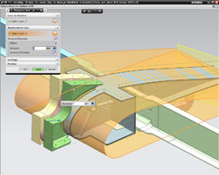
Door Handle Design using PTS Visual Rules-2: The Reuse Library enables users to quickly reuse a wide range of data, but when combined with automation and the Product Template Studio, sub-systems which contain a full range of knowledge and intelligence can also be created
For the 7.5 release, Siemens has extended the application of the HD-3D technology in two key areas. Firstly, it now integrates directly with Teamcenter, so that the full extent of the managed meta data can be used as the basis for queries, allowing users to pretty much find out where, when and how anything is happening within a product under development. For example, data can now be pulled from Teamcenter Requirements (such as specific performance requirements in terms of weight or volume) and the system can run checks automatically with each revision.
The second is that the HD3D-based tools are now much more flexible in the NX environment. Whereas previously Visual Reports could only be used with the appropriate dialog, they can now be interacted with using the assembly Navigator. This means users can work in the way they’re used to, rather than having to adapt to a prescribed workflow.
Simulation and Analysis
Trying to cover the simulation updates in NX 7.5 in a single review is nigh on impossible, but here’s a quick look at what’s becoming a very interesting set of tools that cover a huge range of simulation tasks and industry specialism.
There are several key areas for this release. The first is greater support for Multi-body Dynamics. Users can now include flexible body dynamics in assembly simulations allowing both rigid and flexible bodies to be combined in a single NX Motion simulation. In addition, for those working on systems level simulation, a dynamic link can be created between NX Motion and MATLAB/Simulink, allowing the two to pass data between them in order to create a more accurate simulation.
The second key enhancement is Durability. Fatigue analysis is becoming more widespread in many simulation tools, but for many the process of integrating cyclical loading into a simulation run is a time consuming task. Enter the Durability Wizard, which guides users through the set-up and reporting process to ensure the information is in the right format, where it’s needed.
The final area I want to discuss is the introduction of better tools for combining digital simulation with physical test results. Using the new tools the digital environment can be used to plan out testing processes (measurement points, sensor settings and such) and physical test results can be fed back in the simulation and linked to the digital model. This allows the user to correlate the digital with the physical test results, conduct greater experimentation and for those looking to reduce the number of physical tests, provide greater confidence and the ability to fine tune the simulation process.
Finally, it’s worth noting that the updates that have been made to the modelling environment are also extremely relevant to simulation and Synchronous Technology can pay huge dividends for the simulation-focussed user. Rather than having to rely on traditional modelling techniques for abstraction of models and de-featuring and re-parametrisation, users can dive in and make the required edits without having to worry about having an intimate knowledge of the construction history of the part and assembly. This is going to make the whole process much more efficient.
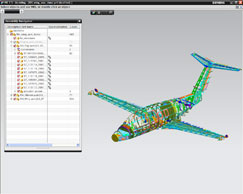
Featuring lightweight JT viewing techniques at its core, NX allows users to work with incredibly large datasets quickly and efficiently
Conclusion
Every time I look at NX I am completely blown away and have the same realisation that while some systems make a lot of noise about how they support an entire industry workflow, NX actually fulfils that vision and all from within a single system.
While Siemens continues to increase the depth of functionality, there is a constant stream of work being done on the user experience, both in terms of simplifying and rationalising functionality and adding new tools to make complex tasks easier to perform. A perfect example of this is the manner in which Synchronous Technology has been expanded in this release to support the creation and modification of complex surfaces. By removing the reliance on history with direct editing tools, it makes light work of what should be a time consuming task.
Finally, to cap things off, the enhancements made to HD3D, which bring clarity and richness to the often overwhelmingly complex and cryptic data we store in our data management system, are impressive. It makes the whole thing work from not only a design and production point of view, but from an organisational level, allowing anyone involved in the product development process to truly engage with the job at hand. In short, it’s another outstanding release.
http://www.siemens.com/plm
| Product | NX 7.5 |
|---|---|
| Company name | Siemens PLM Software |
| Price | on application |


